


4 61190860L1-5BSection 61190860L1-5, Issue 2
Wire-Wrap – The to-facility and from-facility
wire-wraps are an alternate method in lieu of the
amphenol connections.
Customer Side
Amphenol Connection – The to-CPE and from-CPE
amphenols should be left-side oriented to prevent
SCIM panel removal interference after amphenol
installation.
RJ-48C – These modular jacks are an alternate method
in lieu of the amphenol connections.
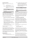
-48 VDC Terminal
Local DC power connects to terminal strip TB1 at the
bottom of the shelf backplane. This power source is
distributed across the backplane to slots 1 through 8
and can jumper to the SCIM TB1 to power the
controller card.
NOTE
Both the shelf backplane and the SCIM card each
have a TB1 terminal strip. This practice identifies
the specific TB1 when referenced in the text.
3. CONFIGURATION
Shelf
There are no configuration selections on the shelf
backplane. If -48 VDC is connected to TB1 on the
shelf card there is no need for the power card unless
for a spare power source.
Power Card
The PWR card has an AC power cord that inserts into
a standard 110 volt AC grounded wall outlet. When
AC power is in use, local power should not be
connected to TB1 on the shelf card. The PWR card
also applies power to the same TB1 shelf terminals,
which in turn can be jumpered to TB1 on the SCIM
card.
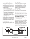
Protect Card
The protect card can receive power from either the
network (span) or from the backplane (-48 VDC). To
initiate the protect feature the card in slot 8 must
support the technology of the channel cards that are
enabled for protection. The protect card should also
have span power capability to power the SCIM should
that configuration be used.
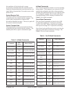
Shelf Cards
Channel cards are individually configured to meet
network or customer requirements. Certain cards only
receive power from network span power. These cards
do not have pin contacts for shelf power.
CAUTION
It must be determined if channel cards can receive
both span power and shelf power. Some cards
may malfunction under that condition.
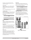
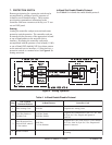
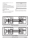
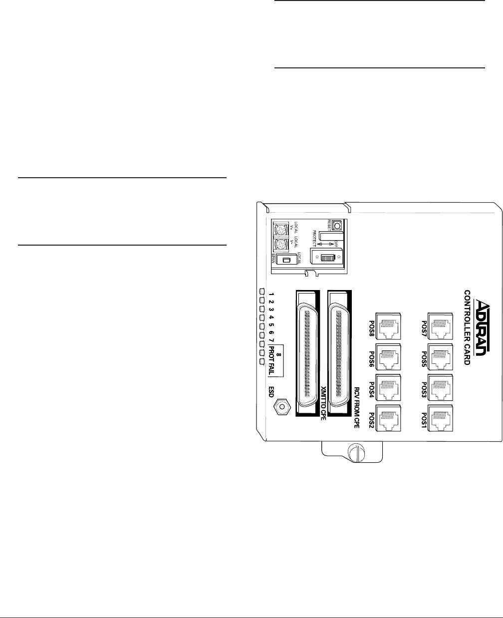
SCIM Controller Card
Option switches on the SCIM controller circuit board
are located behind an access panel. Remove the
housing from the shelf to gain access to the panel’s
thumb screw fastener (refer to Step 1 of the Mounting
Procedure). See Figure 2 for SCIM Card connections,
terminals, indication, and switches.
Figure 2. SCIM Card Elements