


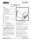

561190860L1-5B Section 61190860L1-5, Issue 2
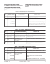
Span Power Switch S1
This switch selects between span power or local
power.
SPAN – The SCIM receives power from the
protect card in slot 8.
LOCAL – The SCIM receives power from local
-48 VDC to terminal strip TB1 on the
SCIM card.
NOTE
Local -48 VDC can be jumpered from the shelf
TB1 terminals.
Protection Select/Reset Switch S2
The first function of this pushbutton switch enables or
disables standby protection for individual slots (1
through 7). Protection for selected slots can be
disabled if cards of a different technology occupy
those slots, or to meet SLA agreements. Protection is
selected using the following procedure:
1. Depress S2 for 5 seconds. Slot 1 LED will start to
flash green; all other LEDs will be OFF. Release
S2.
2. To enable protection for slot 1, press and release
S2. Slot 1 LED will turn solid green and the LED
for slot 2 will begin to flash.
3. To pass over a slot that is not to be protect
enabled, wait several seconds while that slot’s
LED is flashing. The LED turns OFF and the next
LED begins to flash green.
4. Continue this process until the LEDs for all slots
designated for protection are ON.
The protect configuration, once established, is
maintained in memory.
The second function of this switch is to reset the
protect configuration in the event the protect card was
enabled to temporarily replace a malfunctioning shelf
card. After the system is returned to normal,
depressing S2 for a minimum 5 seconds resets the
protect configuration stored in memory. Immediately
release the pushbutton when the LEDs return to the
protect configuration.
Protect Switch S3
This switch controls the protect feature.
ON – All standby and protect functions are active.
OFF – The standby module in slot 8 is cut through
and detection circuitry disabled. If the
standby card was supplying span power to
the SCIM, all the LEDs will be OFF. If the
SCIM was receiving local -48 VDC power,
all the LEDs will flash red.
NOTE
The protect card in slot 8 should have span power
capability either permanent or as an enabled
option.
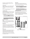
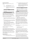
Local Power
Terminal strip TB1 on the SCIM card accepts local -48
VDC power. Installation requires that wiring (14 to 26
AWG) be routed from the back of the SCIM housing.
This arrangement is an alternative to span power the
SCIM receives from the protect card. Slide switch S1
selects between span power or the -48 VDC supply.
SCIM frame ground is attained through a separate
ground terminal.
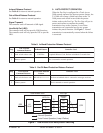
4. OPERATIONAL DESCRIPTION
The SCIM card is a component of the Pro-Cap
assembly that provides T1 drops to the customer
through an RJ-48C or Amphenol connector. The T1
1x7 Controller Card is an enhanced SCIM that also
performs manual 1x7 protection switching on T1
(HDSL) services. The controller card is designed to
function as a manual protection switch and does not
have the capability to address an automatic protection
switch function.
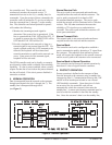
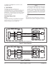
T1 protection switching is accomplished through two
network elements:
• Central Office Element (COE)
• Remote Element (RE).
The COE functions as the master of the protection
switching operation by initiating all commands. The
RE will only respond to the COE commands. The
controller card and a Network Interface Unit (NIU)
represent the RE. A Digital Test Access Unit (DTAU),
a Digital Cross-connect, or a T1 Test Set can represent
the COE.
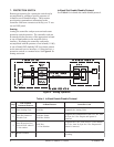
The controller card uses the card in slot 8 of the
Pro-Cap mounting as the standby service. The NIU in
slot 8 will provide the appropriate physical layer
interface to the network (i.e. HDSL2, HDSL, or T1
AMI) and 4-Wire T1 AMI physical layer interface to