


6 61190860L1-5BSection 61190860L1-5, Issue 2
the controller card. The controller card will
continuously monitor the network receive T1
transmission service in slot 8 (i.e. standby line) for
commands. Upon the receipt of these commands, the
controller card will initiate the T1 service switchover
from the requested line (1 through 7) to the standby
line. The controller card when optioned for protect
will conduct the following:
1. Monitor the incoming network signal to
determine if the protect line is operational. If the
line is operational the FAIL LED will be OFF. If
no signal is present, the slot 8 PROT LED will be
OFF and the FAIL LED will be ON.
2. Provide a loopback to the network as long as a
transmit signal is not present from the CPE. If a
signal is placed on the slot 8 CPE transmit to the
network, the loopback will be released and
normal transmission to and from the network can
occur. Upon removal of the transmit signal,
loopback will be activated.
The SCIM controller card can be locally or remotely
provisioned to either enable or disable slot-switching
capability. If a slot is protect enabled, when a switch
request for that slot is received on the protect channel,
the slot will switch. If the slot is protect disabled, it
cannot be switched.
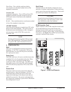
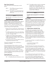
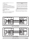
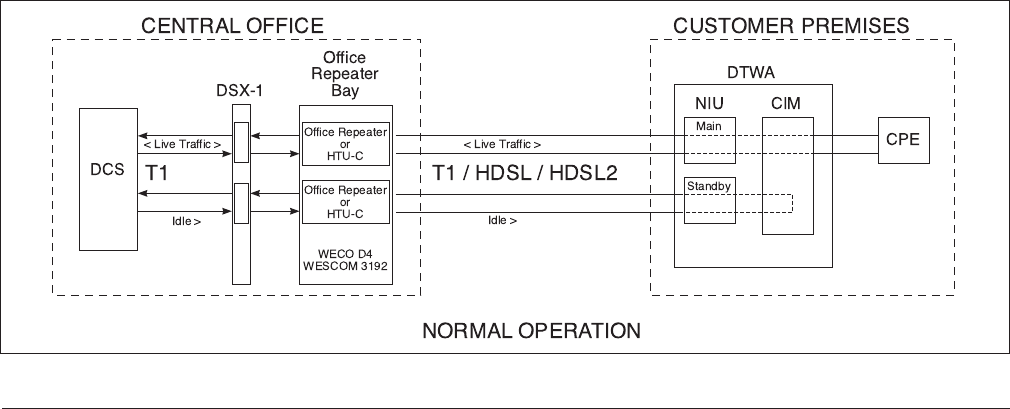
5. NORMAL OPERATION
Data is transported from the network to the customer
through an assigned slot (slot 1 through slot 7). The
standby line is transported through slot 8
(see Figure 3).
Normal Receive Path
The receive path is non-protected and transformer
coupled between the network and the customer. The
receive path is monitored for in-band or ESF
bit-patterned datalink messages. The receive path
toward the network will be terminated with a 100 ohm
resistor. This 100 ohm termination increases the
reliability of T1 signal recovery and minimizes
crosstalk. The receive path toward the customer will
be an open termination.
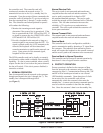
Normal Transmit Path
The transmit path is non-protected and transformer
coupled between the network and the customer.
Passive Mode
The controller card can be configured to establish a
passive transmission path by detecting a T1 signal from
the customer. The transition from normal to passive
mode will require the loopback to the network removed
and the receive path to the customer to be reconnected.
Passive Mode to Normal Operation
The controller card will return to normal operation by
detection of a loss-of-signal from the customer.
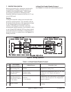
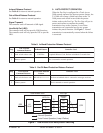
6. PROTECT OPERATION
Protect operation is defined as the transport of data
from the network to the customer using a standby line
connected to Slot 8. Communication between the COE
and RE will be based upon in-band or out-of-band
(ESF datalink) commands. Upon detection of a fault
on an active line, the controller card will not
automatically switch the customer’s data onto the
standby line. A remote provisioning command must be
used to switch the customer’s data onto the standby
line. Once the customer’s data is on the standby line,
Figure 3. Normal Operation