


6 61223445L1-5D
Connections 239 H4R Installation and Maintenance Practice
4. CONNECTIONS
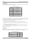
All connections are made through card edge connectors.
Table 3 provides the card edge pin assignments.
CAUTION
The H4R dissipates a maximum of 5.4 watts.
NOTE
Ensure that the chassis ground is securely connected to the apparatus case. Ground
pin designations are defined in Table 3.
5. HDSL4 DEPLOYMENT GUIDELINES
Refer to the H4TU-C Installation and Maintenance Practice, HDSL4 Deployment Guidelines section, for loop
parameters including attenuation and loop resistance considerations.
NOTE
The H4TU-C with part numbers 1221401L6, 1221403L6, and 1221404L6 support
only one H4R in the HDSL4 circuit.
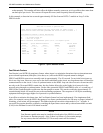
Refer to the Detailed Status Screen by accessing the menus on the H4TU-C craft terminal interface for current
Signal-to-Noise Ratio Margin and Attenuation status indications for the circuit.
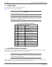
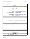
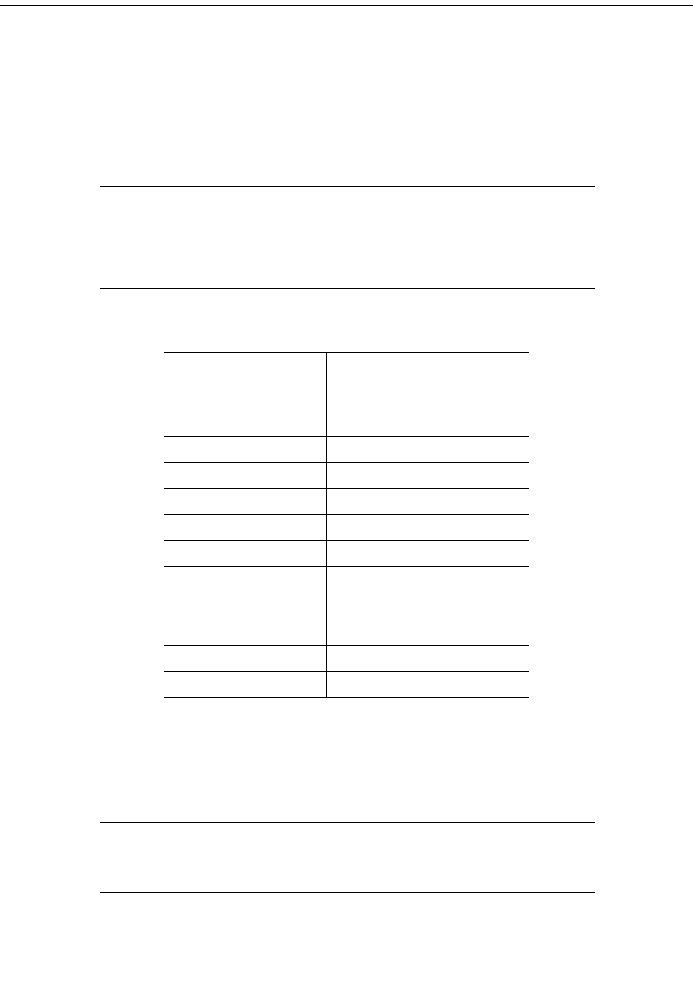
Table 3. H4R Card Edge Pin Assignments
Pin Designation Description
1 GND Ground
2 NC No Connect
3 T1 Customer Loop 1 Tip
4 R1 Customer Loop 1 Ring
5 T1 Network Loop 1 Tip
6 R1 Network Loop 1 Ring
7 NC No Connect
8 T Network Loop 2 Tip
9 R Network Loop 2 Ring
10 GND Ground
11 T Customer Loop 2 Tip
12 R Customer Loop 2 Ring