


Chapter 1. Introduction
1-4 DSU 56/64 User Manual 61200062L1-1
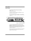
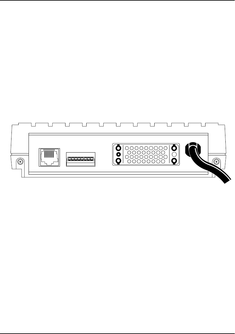
REAR PANEL
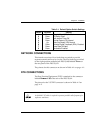
The rear panel of the DSU 56/64 is shown in Figure 1-2.
P
RIMARY
V.35, a thirty-four pin connector, provides the
synchronous DTE interface.
The eight-pin modular jack (RJ-48S) labeled T
ELCO
connects the
DSU 56/64 to the DDS network.
For pinouts to these connectors, see Table A-1, Pinouts for RJ-48S
Network Connections, on page A-1 and Table A-2, V.35 DTE Pinouts,
on page A-2.
Figure 1-2. DSU 56/64 Rear Panel
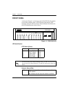
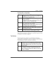
All setup or configuration parameters for the DSU 56/64 are
selected with an eight-position DIP switch. This switch, labeled
O
PTIONS
, is accessible from the rear panel. The label also references
the options chart located on the bottom of the unit. The individual
options are explained in detail in Chapter 2 in the section
Configuration on page 2-2.
The power cord on the rear panel of the DSU 56/64 is mechanically
secured to the back panel and provides the connections to the
integral AC/DC power supply.
12345678
115 VAC
60HZ .06A
TELCO OPTIONS
(LISTED ON BOTTOM)
PRIMARY V.35