


Chapter 2. Installation
61200062L1-1 DSU 56/64 User Manual 2-5
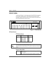
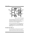
NETWORK CONNECTIONS
This interface consists of four leads that are paired to provide
separate transmit and receive circuits. The four leads are provided
on the eight-position modular jack DSU RJ-48S labeled T
ELCO
on
the rear panel of the DSU 56/64.
The pinouts for this connector are shown in Table A-1 on page A-1.
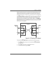
DTE CONNECTIONS
The Data Terminal Equipment (DTE) is attached to the connector
labeled P
RIMARY
V.35 at the rear of the DSU 56/64.
The pinout for the V.35 DTE connector is shown in Table A-2 on
page A-2.
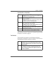
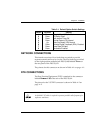
Table 2-1. Default Option Switch Settings
Switch Position Setting
1
2
3
4
5
6
7
8
Down
Down
Down
Down
Up
Down
Down
Down
Clear to Send (CS) Normal
CS Delay Short
Anti-stream Timer Off
Carrier Detect (CD) Normal
Data Set Ready (SR) Normal
Remote Digital Loopback (RDL) Enabled
Loop Rate 56 Kbps
Scrambler Enabled
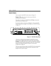
A shielded V.35 cable is required to prevent possible radio frequency in-
terference emissions.