


Chapter 3. Test Modes
3-4 DSU 56/64 User Manual 61200062L1-1
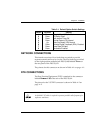
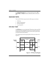
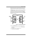
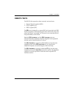
Figure 3-2. DTE with TP Test Diagram
The internal test pattern generator and detector of the DSU 56/64
operate with a 2047 data pattern. When this test is initiated, the test
pattern detector examines the receive data stream until
synchronization to the 2047 pattern occurs. Once synchronized, the
detector continues to check the receive data and reports any
detected bit errors by turning on the E
RROR
LED.
Once a test is initialized with the internal test pattern generator and
detector, errors can be injected into the transmit data stream by
pressing S
ELECT
and observed by watching the E
RROR
LED turn
on for a brief period of time. As previously mentioned, the DTE
WITH
TP is automatically performed during the self-test sequence
for the DSU 56/64.
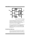
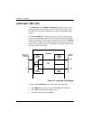
DTE AND LOOP TEST (LL)
This test is initiated at the local DSU 56/64 and allows independent
testing of the separate sections of the DSU 56/64. This includes
testing of the local DTE interface with data from the terminal or test
equipment and testing of the loop interface section of the local DSU
56/64 DSU
DTE
Receive
Interface
DTE
Transmit
Interface
Test
Pattern
Generator
Test
Pattern
Detector
Loop
Transmit
Interface
Loop
Receive
Interface
DTE
with
Test Pattern
TD
DTE or Test
Equipment
Interface
Network
Interface
RD
Loop TX
Loop RX