


Loop Connections
61181307L7-5E 5
LOOP CONNECTIONS
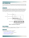
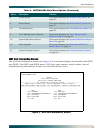
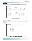
The T1 loop connections are made through four RJ-48C type connectors. For each connector,
transmit tip and ring are on pins 5 and 4, and receive tip and ring are on pins 2 and 1, respec-
tively. The single-mode fiber is connected to the SC connector located on the back panel of the
unit.
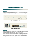
OPERATION
The Quad Fiber Remote (QDFR) Unit provides a platform to exchange data between four Tls
and an optical fiber interface. The customer data connection is via the RJ-48C connectors on
the unit. An optical fiber interface is provided for communication with the loop. The Quad
Fiber Remote (QDFR) Unit operates with a QDFC module at the other end of the fiber optic
cable. The figure below illustrates the pin-out configuration for the RJ-48C connectors.
Figure 3. RJ-48C Pinout Configuration
Power Interface
The power for the QDFR can be supplied through a –48 VDC supply connected to the back of
the QDFR. The QDFR can be powered from –24 VDC to –48 VDC.
Diagnostics
There are several options available for diagnostics:
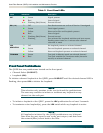
• Front panel LEDs (see Table 2 on page 4)
• “Loopback and Test Commands Menu” on page 12
• “Performance History Menu” on page 16
• “Troubleshooting Menu” on page 22
T
R
T1
R1
12345678
R T R1 T1
T
o Network
Receive from Network
Reserved for Future Use
Transmit to Network
Miniature 8-Position Plug
To Registered Terminal Equipment