


61181307L7-5E B-1
Appendix B
Rear Panel DS1 Test Access
GENERAL
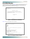
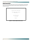
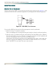
Figure B-1 through Figure B-3 provides a graphical description of the test jack functionality
for the QDFR. The test jack can be provisioned to correspond to any of the four T1 channels.
There are two options for selecting the T1 channel to be “connected” to the test jack.
• The first is the front panel switch for channel selection (
CH SELECT). The LED for the T1
channel will flash if that is the selected channel for the test jack.
For example, if T1 channel 4 corresponds to the test jack, the LEDs for DS1 1, 2, and 3
remain solid while the LED for DS1 4 flashes.
To change the selected channel, momentarily press the
CH SELECT switch until the desired
channel’s LED indicator flashes.
• The next option for selecting test jack channel operation is from the Loopbacks and
Test\Test Port (Bantam Jack) Control screen. The parameter for this option is Change Test
Port Number.
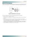
The test jacks can operate as either a terminate jack, also known as intrusive mode, or as a
monitor jack, also known as non-intrusive mode. The functionality of the test jack is
dependent on the provisioning of Test Jack Mode found under Loopbacks and Test\Test Port
(Bantam Jack) Control.
• If this parameter is set to “Monitor”, the test jack can be utilized to monitor the Tx data
from the network or from the customer.
• If the parameter is set to “Intrusive”, the test jack can be utilized to connect a test set to
allow transmitting and receiving data for troubleshooting purposes.
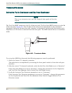
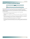
In Intrusive mode, the direction of the test jack must also be selected. This parameter is
set when Toggle Intrusive Test Direction is changed.
– If the test direction is “Network”, the Tx and Rx data is to and from the network
equipment.
– If the test direction is set to “Customer”, the Tx and Rx data is to and from the customer’s
equipment. Further description of each mode is found on the following pages.