1Section 61245201L1-5, Issue 361245201L1-5C
FNID and T200 FNID
Fractional T1 Network Interface Device
Installation and Maintenance
CONTENTS
1. GENERAL ............................................................................ 1
2. INSTALLATION.................................................................. 2
3. CONNECTIONS................................................................... 3
4. DSL SYSTEM TESTING .................................................... 4
5. CONTROL PORT OPERATION......................................... 4
6. DSL DEPLOYMENT GUIDELINES ................................. 11
7. TROUBLESHOOTING PROCEDURES ........................... 12
8. MAINTENANCE ................................................................ 12
9. PRODUCT SPECIFICATIONS .......................................... 12
10. WARRANTY AND CUSTOMER SERVICE .................... 12
Appendix A. FT1 Loopbacks ................................................... A-1
FIGURES
Figure 1. ADTRAN FNID ...................................................... 1
Figure 2. FNID Option Switch Locations .............................. 2
Figure 3. FNID Network Loop Connection Locations .......... 4
Figure 4. RS-232 (DB9) Pin Assignments ............................. 4
Figure 5. Introductory Menu Screen ...................................... 7
Figure 6. HDSL Main Menu Screen ...................................... 7
Figure 7. Current System Status Screen................................. 8
Figure 8. Performance History Screen ................................... 8
Figure 9. Loopback Options Screen ....................................... 9
Figure 10. Self Test Options Screen ........................................ 9
Figure 11. Provisioning Options Screen ................................. 10
Figure 12. Troubleshooting Screen ......................................... 10
Figure 13. DSL Deployment Guidelines................................. 11
Figure A-1. FT1 Loopbacks .................................................... A-1
Figure A-2. FT1 DP Network Loopback................................. A-1
Figure A-3. FT1 DP CPE Loopback ....................................... A-1
Figure A-4. FT1 Repeater #1 or # 2 Network Loopback ........ A-2
Figure A-5. FNID Network Loopback .................................... A-2
Figure A-6. FNID CPE Loopback ........................................... A-2
TABLES
Table A. Front Panel Functions ............................................. 3
Table B. FNID Card Edge Pin Definitions ........................... 3
Table C. Definition of Screen Abbreviations ........................ 5
Table D. Loop Insertion Loss Data....................................... 11
Table E. Troubleshooting Guide .......................................... 12
Table F. FNID Unit Specifications ...................................... 13
Table A-1. FT1 Loopback Select Codes ................................ A-3
1. General
This practice is an installation and maintenance (I/M)
guide for the ADTRAN Fractional T1 Network
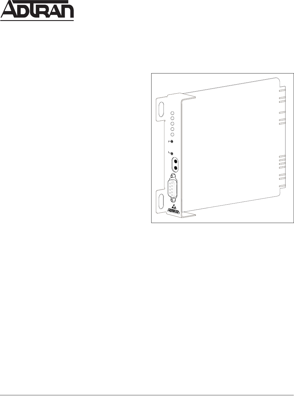
Interface Device (FNID). Figure 1 is an illustration of
the ADTRAN FNID.
Revision History
This practice has been reissued to reflect additional
support detail for two FT1 repeater applications.
The ADTRAN FNID is a network terminating unit
used to deploy a fractional T1 circuit using 2-wire
metallic facilities on CSA loops. This practice is
written to support both the T200 FNID circuit pack
(P/N 1245201L1) and the FNID standalone
(P/N 4245201L1) units.
The FNID is housed in a standalone metal enclosure.
The T200 FNID card plugs into a standard Type
200/400 multiple mounting shelf.
Section 61245201L1-5C
Issue 3, September 1999
CLEI Code: NCDIFBH4 _ _
Trademarks: Any brand names and product names included in this document are
trademarks, registered trademarks, or trade names of their respective holders.
Figure 1. ADTRAN FNID
DSL
FNID
1245201L1
DS1
SF
AMI
(GRN)
(GRN)
ESF
B8ZS
(YEL)
(YEL)
LBK
LOC
L
B
K
REM
R
S
2
3
2
TX
RX
M
O
N


