


4 Section 61245201L1-5, Issue 3 61245201L1-5C
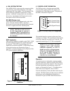
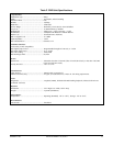
5. CONTROL PORT OPERATION
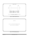
The FNID provides a faceplate-mounted DB9
connector that supplies an RS-232 interface for
connection to a controlling terminal. The pinout of
the DB9 is illustrated in Figure 4.
The terminal interface operates at data rates from
2.4 kbps to 19.2 kbps. The asynchronous data format
is fixed at 8 data bits, no parity, and 1 stop bit. The
supported terminal type is VT-100 or compatible.
NOTE: If you are using a personal
computer (PC) with terminal
emulation capability, be sure to
disable any power saving programs.
Otherwise, communication between
the PC and the HDSL unit may be
disrupted, resulting misplaced
characters or screen timeouts.
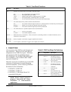
Operation
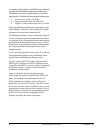
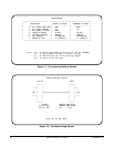
A terminal session is initiated by entering multiple
space bar characters, which are used by the FNID to
determine the speed of the terminal. Once the speed
has been determined, an Introductory menu will
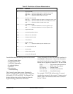
appear, as illustrated in Figure 5. For abbreviations
used in the screen diagrams, refer to Table C.
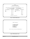
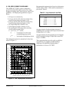
From the Introductory menu, the Main menu may be
selected. The Main menu provides access to detailed
performance and configuration information, as
illustrated in Figure 6, HDSL Main Menu Screen.
4. DSL SYSTEM TESTING
The ADTRAN DSL system provides extensive ability
to monitor the status and performance of the DS1
signals and DSL loop signals. The front panel LEDs
on the FNID are explained in subsection 2 of this
practice. Additional testing features are described in
this section. Specifically, the Bantam jacks on the
front panel of the FNID are described.
DS1 MON Bantam Jack
The FNID provides a dual Bantam jack on the front
panel. This jack, labeled “MON,” provides a
non-intrusive access point for monitoring the transmit
and receive signals at the DS1 interface point.
NOTE: MON Rx provides access to
the DS1 input from the customer’s
equipment. MON Tx provides access
to the DS1 output of the FNID toward
the customer.
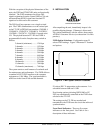
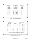
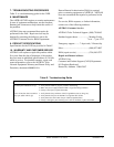
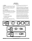
FNID Loopbacks
There are two loopbacks available to the FNID. FNID
network loopback loops the FT1 signal back toward
the network. FNID CPE loopback loops the FT1
signal back toward the customer. FNID network loop
connection locations are illustrated in Figure 3.
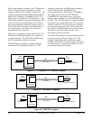
Appendix A contains diagrams and descriptions of the
FT1 system loopback capabilities.
Figure 3. FNID Network Loop Connection
Locations
Figure 4. RS-232 (DB9) Pin Assignments
6
7
8
9
1
2
3
4
5
TXD (Transmit Data)
RXD (Receive Data)
SGN (Signal Ground)
T1 TO CPE
R1 TO CPE
T FROM CPE
R FROM CPE
T1 LOOP1
R1 LOOP1
GND
-48V
DS1
DS1