


3Section 61245201L1-5, Issue 361245201L1-5C
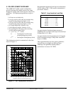
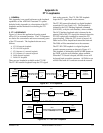
3. CONNECTIONS
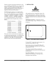
All connections of the FNID are made through card
edge connectors. Table B gives the card edge pin
assignments for the FNID circuit pack. The circuit
pack operates in either the standalone chassis
(P/N 1242034L2), the ADTRAN HR4 HDSL shelf
(P/N 1242008L1), or the ADTRAN HR12 HDSL
shelf (P/N 1242007L1).
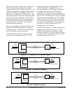
When the circuit pack is installed in any of the FNID
enclosures, all connections are made through the
enclosure backplanes. See the following ADTRAN
documents for more information:
• 61242007L1-5, HR12 I/M
• 61242008L1-5, HR4 I/M
• 61242034L2-5, T400 Single Mount I/M
(removable RJ-48 jacks)
NOTE: Ensure chassis ground is
properly connected for either
standalone or shelf-mounted
applications.
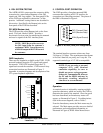
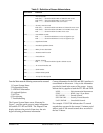
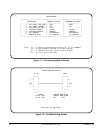
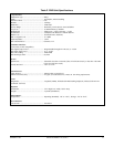
Pin Designation Description
1 ................. CH GND .......... Chassis ground
5 ................. DS1-T1 ............ DS1 Receive Out tip
(to Customer Interface)
7 ................. H1-T ................ DSL Loop Tip (facility)
11 ............... CH GND .......... Chassis ground
13 ............... H1-R ................ DSL Loop ring (facility)
15 ............... DS1-R1 ............ DS1 Receive Out ring
(to Customer Interface)
17 .......................................... -48 Return
27 ............... FG .................... Frame Ground
35 .......................................... -48 VDC
49 ............... DS1-R .............. DS1 Transmit In ring
(from Customer Interface)
55 ............... DS1-T .............. DS1 Transmit In tip
(from Customer Interface)
Table B. FNID Card Edge Pin Definitions
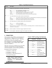
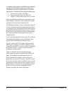
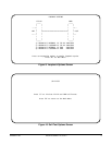
Table A. Front Panel Functions
Indicator
DSL .................
DS1 ..................
LBK .................
RS-232 .............
REM LBK .......
LOL LBK ........
Description
Indicates five possible states of the quality of the DSL signal
Off ........................ No synchronization of FT1 DP and FNID
Red........................ Poor signal quality (≥10
-7
BER)
Yellow .................. Marginal signal quality (≤2 dB margin above 10
-7
BER)
Green .................... Good signal quality (≤2 dB margin above 10
-7
BER)
Blinking ................ An error detected on the loop will cause this LED to blink briefly
This LED indicates three possible conditions described below.
Off ........................ The customer-side DS1 signal is absent or in a format that does not match the provisioned options
Blinking ................ Indicates an error has been detected on the DS1 interface
On Solid ............... The customer-side DS1 signal is present and synchronized
This LED indicates two possible loopback states as described below.
Off ........................ Unit is not in loopback
On Solid ............... Local (FNID) loopback is active
DB9 connector for craft interface. Allows connection to controlling terminal. For further information, refer to
subsection 6 of this practice.
Remote Loopback. Push button to toggle Loopback active/inactive.
Local Loopback. Push button to toggle Local Loopback active/inactive.