


EKI-7657C _Manual_ed1 18
2.4 Network Connection
The EKI-7657C has 7 x RJ-45 ports that support connection to 10 Mbps Ethernet, or
100 Mbps Fast Ethernet, and half or full duplex operation. EKI-7657C can be
connected to other hubs or switches via a twisted-pair straight-through or crossover
cable up to 100m long. The connection can be made from any TX port of the EKI-
7657C (MDI-X) to another hub or switch either MDI-X or uplink MDI port.
The EKI-7657C supports auto-crossover to make networking more easy and flexible.
You can connect any RJ-45 (MDI-X) station port on the switch to any device such as a
switch, bridge or router.
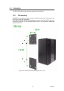
2.5 Connection to a Fiber Optic Network
EKI-7657C has three SFP slots for connecting to the network segment with single or
multi-mode fiber. You can choose appropriate SFP transceiver to plug into the slot.
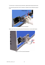
Make sure the transceiver is aligned correctly and then slide the transceiver into the
SFP slot until a click is heard. You can use proper multi-mode or single-mode fiber
according to the used SFP transceiver. With fiber optic, it transmits speed up to 1000
Mbps and you can prevent noise interference from the system and transmission
distance up to 110 km, depending on the SFP transceiver.
The small form-factor pluggable (SFP) is a compact optical transceiver used in optical
communications for both telecommunication and data communications applications.
Note
The SFP/Copper Combo port can’t be both used at the same time. The SFP port has the
higher priority than the copper port; if you insert the 1000M SFP transceiver (which is
being connected to the remote device) into the SFP port, the connection of the
accompanying copper port will link down.
If you insert the 100M SFP transceiver into the SFP port even without a fiber connection
to the remote, the connection of the accompanying copper port will link down
immediately.
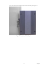
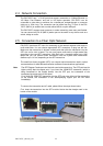
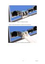
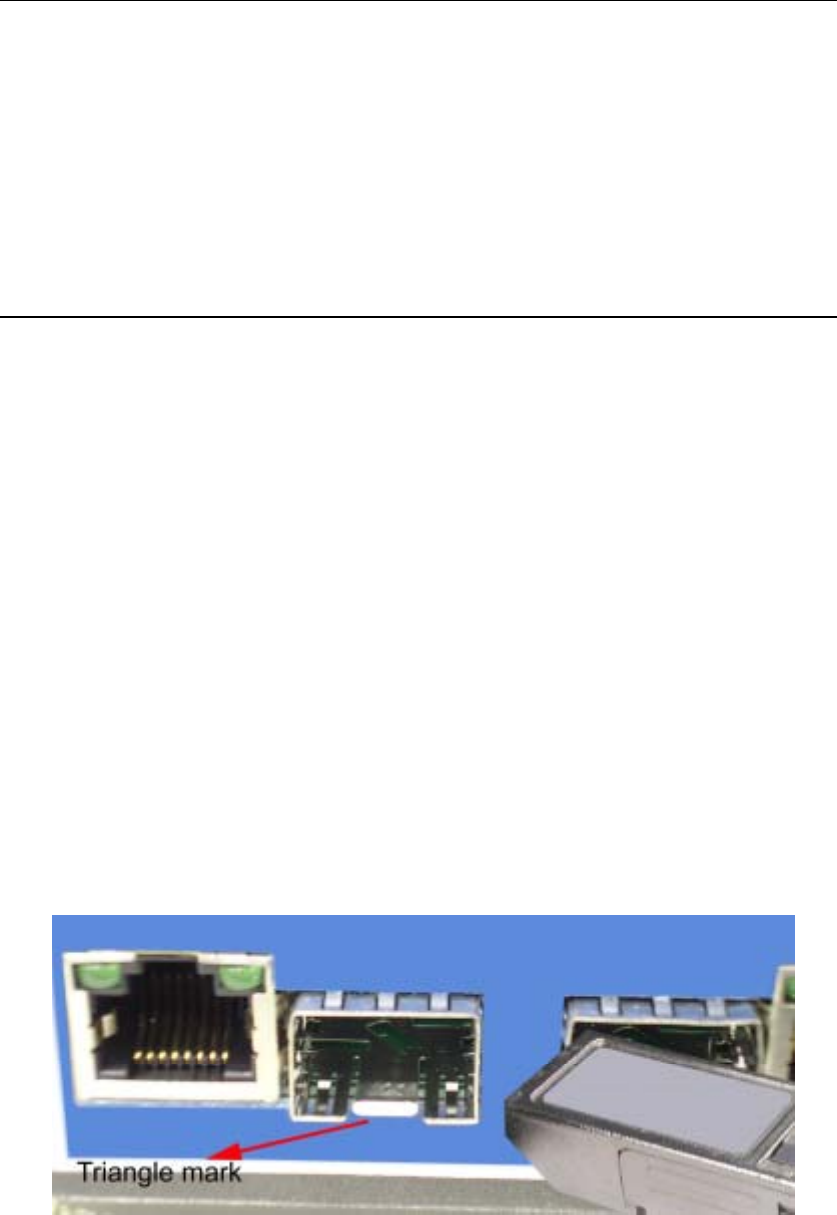
To connect the transceiver and LC cable, please follow the steps shown below:
First, insert the transceiver into the SFP module. Notice that the triangle mark is the
bottom of the module.
Figure 2.8: Transceiver to the SFP module