


MIC-3043 User Manual 24
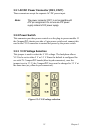
3.5.4 Fan Module Connector
The FAN connectors provide +12 V power for fan operation and relay the
tachometer output from the fans.
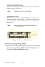
3.5.5 Alert indicators
The MIC-3043 series alarm module (MIC-3924L-A) provides two alert
signals to the chassis front panel, close to the HDD bay. The bottom sig-
nal is for fan failure; the upper signal is for system overheating (tempera-
ture above 50 ºC).
Figure 3.6: Location of alert indicators
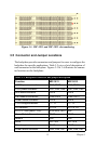
3.6 Clock Routing Configuration
The backplane is configured to comply with the clock routing specified in
the CompactPCI Specification, PICMG 2.0, R3.0. This Specification
requires that each slot be independently clocked.
Note:
The fan4 is reserved as factory default.
Note:
System temperature is detected by the alarm mod-
ule via the LM75 chip.