


ix Table of Contents
Contents
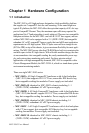
Chapter 1 Hardware Configuration................................ 2
1.1 Introduction....................................................................... 2
1.2 Features ............................................................................. 3
1.3 Specifications .................................................................... 3
1.3.1 General ...........................................................................3
1.3.2 Hot-swap Fans ............................................................... 4
1.3.3 Power Supply ................................................................. 4
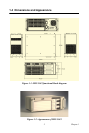
1.4 Dimensions and Appearance............................................. 5
Chapter 2 Installation ....................................................... 8
2.1 Initial Inspection................................................................ 8
2.2 The MIC-3043 Illustration ................................................8
2.3 Installation Procedures...................................................... 9
2.3.1 Card Installation and Removal ......................................9
2.3.2 Before Operating the System ....................................... 11
2.3.3 Installing a 3.5" Hard Disk Drive ................................11
2.3.4 Connecting the rear I/O module ................................... 12
2.3.5
Configuring the built-in RAID (SCSI) by RIO module
(MIC-3043C series only)
................................................. 12
2.3.6
Configuring the built-in IDE for the RIO module
(MIC-3043A and IC-3043B series)
.................................. 13
Table 2.1: HDD number for type A..............................13
Table 2.2:HDD number for type B............................... 13
Figure 2.5:IDE adaptor (type B .................................... 14
2.3.7 Configuring the built-in SATA for the RIO module
(MIC-3043D series) .................................................... 14
Figure 2.6:The location of jumper switch..................... 14
Figure 2.7: Setting table for IDE/SATA selection........14
2.3.8 Replacing the Hot-swap Fan ........................................15
Figure 2.8: Hot-swappable fan maintenance15
Chapter 3 Backplane....................................................... 18
3.1 General Information........................................................ 18
3.2 Features ........................................................................... 18
3.3 Specification.................................................................... 18
3.4 Slot Assignments............................................................. 19
Table 3.1:
System to peripheral slot signal assignment
...... 20
Figure 3.1:
MIC-3811 and MIC-3812 slot numbering
........ 21
3.5 Connector and Jumper Locations.................................... 21
Table 3.2:
Backplane connector and jumper description
....21
3.5.1 AC/DC Power Connector (CN3, CN17) ...................... 23
3.5.2 Power Switch ...............................................................23