


PCE-5120 User Manual 20
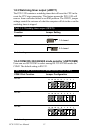
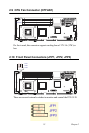
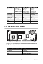
2.4 Parallel Port (LPT1)
The parallel port is normally used to connect the single board computer to
a printer. The PCE-5120 includes an onboard parallel port, accessed
through a 26-pin flat-cable connector, LPT1. The card comes with an
adapter cable which lets you use a traditional DB-25 connector. The cable
has a 26-pin connector on one end and a DB-25 connector on the other,
mounted on a retaining bracket. The bracket installs at the end of an
empty slot in your chassis, giving you access to the connector.
The parallel port is designated as LPT1, and can be disabled or changed
to LPT2 or LPT3 in the system BIOS setup.
To install the bracket, find an empty slot in your chassis. Unscrew the
plate that covers the end of the slot. Screw in the bracket in place of the
plate. Next, attach the flat-cable connector to LPT1 on the CPU card.
Wire 1 of the cable is red or blue, and the other wires are gray. Make sure
that wire 1 corresponds to pin 1 of LPT1. Pin 1 is on the upper right side
of LPT1.
JFP3
JFP2
JFP1
LPT1
LPT1