


PCE-5120 User Manual 24
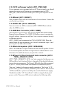
2.10.1ATX soft power switch (JFP1 / PWR_SW)
If your computer case is equipped with an ATX power supply, you should
connect the power on/off button on your computer case to (JFP1 /
PWR_SW). This connection enables you to turn your computer on and
off.
2.10.2Reset (JFP1 / RESET)
Many computer cases offer the convenience of a reset button. Connect the
wire for the reset button.
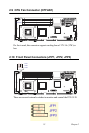
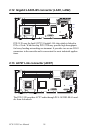
2.10.3HDD LED (JFP2 / HDDLED)
You can connect an LED to connector (JFP2 / HDDLED) to indicate
when the HDD is active.
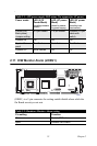
2.10.4SM Bus Connector (JFP2 / SNMP)
This connector is reserved for Advantech's SNMP-1000 HTTP/SNMP
Remote System Manager. The SNMP-1000 allows users to monitor the
internal voltages, temperature and fans from a remote computer through
an Ethernet network.
(JFP2 / SNMP) can be connected to CN19 of SNMP-1000. Please be
careful about the pin assignments, pin 1 must be connected to pin 1 and
pin 2 to pin 2 on both ends of cable.
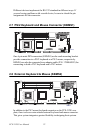
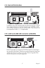
2.10.5External speaker (JFP2 / SPEAKER)
(JFP2 / SPEAKER) is a 4-pin connector for an external speaker. If there
is no external speaker, the PCE-5120 provides an onboard buzzer as an
alternative. To enable the buzzer, set pins 3-4 as closed.
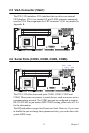
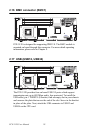
2.10.6Power LED and keyboard lock connector (JFP3 /
PWR_LED&KEY LOCK)
(JFP3 / PWR_LED&KEY LOCK) is a 5-pin connector for the power on
LED and Key Lock function. Refer to Appendix B for detailed informa-
tion on the pin assignments. The Power LED cable should be connected
to pin 1-3. The key lock button cable should be connected to pin 4-5.
There are 3 modes for the power supply connection. The first is “ATX
power mode”, system is on/off by a tentative power button. The second is
“AT Power Mode”, system is on/off by the switch of the Power supply.
The third is another “AT Power Mode” which is using the front panel
power switch. The power LED status is indicated as following table: