


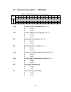


51
DI0 latch
A rising edge on the board's DI0 line will latch the counter value for
the channel.
DI1 latch
A rising edge on the DI1 line will latch the counter value for the
channel.
DI2 latch
A rising edge on the board's DI2 line will latch the counter value for
the channel.
DI3 latch
A rising edge on the DI3 line will latch the counter value for the
channel.
Timer latch
The card latches the counter value on a rising edge of pulses from the
card's on-board timer.
D.5 Counter reset value
Bit 4 (RF) of registers BASE+00H, 04H, 08H and 0CH control the
initial (reset) value of for each counter. You can select either 00000000
or 80000000 (hex). When the counter is reset, it will take this value.
When RF=0, the counter will reset to 80000000h.
When RF=1, the counter will reset to 00000000h.
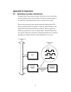
D.6 Timer function
The card can generate an interrupt to the system based on a signal from
its digital inputs, overflow/underflow and over-compare / under-
compare of its counters, or on a programmed time interval. It can
repeatedly generate interrupts at any time interval you specify, from 20
microseconds to 51 second. These interrupts let you precisely monitor
the speed of a control system.