


17 Chapter 2 Installation
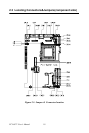
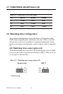
2.13 Floppy drive connector (CN3)
You can attach one 3.5" floppy drive to the the PCI-6872's onboard con-
troller. This is useful for notebooks, for example.
A daisy-chain drive cable converter (part no. 9681000044) is required for
a single floppy system. A 34-pin flat-cable connector is fitted on one end
of the cable converter, while the other end has one floppy disk drive con-
nector. It consists of a 34-pin flat-cable connector (for the 3.5" drives).
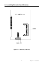
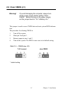
2.13.1 Connecting the floppy drive
1. Plug the 34-pin flat-cable connector into the cable converter. Make
sure that the red wire corresponds to pin 1 on the connector.
2. Attach the appropriate conector at the other end of the cable to the
floppy drive(s). You can use only one connector in the set. The set at the
other end (after the twist in the cable) connects to the A: drive.
When connecting a 3.5" floppy drive, you may have some difficulties in
determining which pin is number one. Look for a number on the circuit
board indicating pin number one. In addition, you should check if the
connector on the floppy drive has an extra slot. If the slot is up pin num-
ber one should be on the right. Please refer to any documentation that
came with the drive for more information.
If your cable needs to be custom made, you can find the pin assignments
for the board's connector in Appendix C.
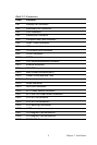
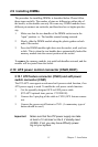
2.14 IDE connector(CN1,CN2)
The PCI-6872 provides two IDE channel to which you can attach up to
four Enhanced Integrated Device Electronics hard disk drives or
CDROM to the PCI-6872’s internal controller. The PCI-6872's IDE con-
troller uses a PCI interface. This advanced IDE controller supports faster
data transfer, PIO Mode 3 or Mode 4, UDMA 33/66/100 mode.
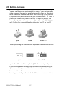
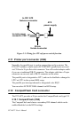
2.14.1 Connecting the hard drive
Connecting drives is done in a daisy-chain fashion. The cable depending
on the drive size. 1 x 40-pin flat cable(p/n: 1701400452) is packing in
PCI-6872's package.
Wire number 1 on the cable is red or blue, and the other wires are gray.
1. Connect one end of the cable to CN1,CN2. Make sure that the red
(or blue) wire corresponds to pin 1 on the connector, which is
labeled on the board (on the right side).