


39
continuously supplied with reliable and “clean” voltage with no
interruptions in this operating mode.
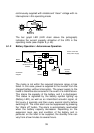
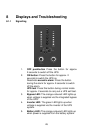
The bar graph LED (LED chain above the pictograph)
indicates the current capacity utilisation of the UPS in this
operating mode (see chapter 8, p. 45).
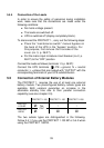
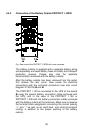
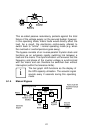
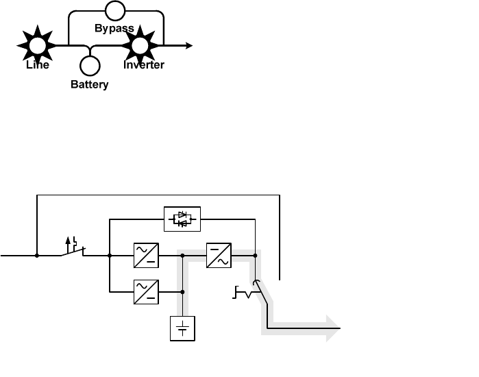
6.1.2 Battery Operation / Autonomous Operation
Battery
Load
REC
REC INV
Manual
bypass
Manual bypass path
SBS
Mains input
miniature circuit
breaker
Mains
Schematic
diagram
Secured
busbar
Load
Power circuit with
faulty mains supply
The mains is not within the required tolerance range or has
failed. In this case, power is supplied to the inverter from the
charged battery without interruption. The power supply to the
loads is therefore also ensured in the event of a mains failure.
This drains the capacity of the battery and it is discharged.
This status is signalled by the battery symbol lighting up
(Battery LED), as well as an intermittent acoustic signal, at
first every 4 seconds and then every second shortly before
switching off. The initial alarm can be suppressed by pressing
the “Alarm off” button. The alarm is automatically reactivated
when the battery capacity decreases. Depending on the
expansion level, age and condition of the battery and in
particular on the load to be supplied, the standby time can
vary from a few minutes to several hours.