


Chapter 1
Getting Started with the Agilent E1364A
Using This Chapter
This chapter includes a Form C Switch description, addressing guidelines,
and an example program to check initial operation. Chapter contents are:
• Instrument Definition. . . . . . . . . . . . . . . . . . . . . . . . . . . . . . . Page 11
• Programming the Switch . . . . . . . . . . . . . . . . . . . . . . . . . . . . Page 13
• Initial Operation . . . . . . . . . . . . . . . . . . . . . . . . . . . . . . . . . . . Page 15
Instrument Definition
Agilent plug-in modules installed in an Agilent mainframe are treated as
independent instruments each having a unique secondary GPIB address.
Each instrument is also assigned a dedicated error queue, input and output
buffers, status registers and, if applicable, dedicated mainframe memory
space for readings or data. An instrument may be composed of a single
plug-in module or multiple plug-in modules (for a Switchbox or Scanning
Voltmeter Instrument).
Switch Description The Agilent E1364A 16-Channel Form C Switch Module is a B-Size
VXIbus and VMEbus register-based product which can be used for
switching/scanning, control, and digital output applications. The switch can
operate in a B-Size VXIbus or VMEbus mainframe or (with an adapter) in a
C-Size VXIbus mainframe. The module has 16 channels of Form C relays.
Each channel includes a relay with common (C), normally open (NO), and
normally closed (NC) contacts.
For the Form C Switch, switching consists of opening or closing a channel
relay to provide alternate connections to user devices. Scanning consists of
closing a set of relays, one at a time. By adding jumpers and
pullup/pulldown resistors, the switch can be used to control external user
devices or as a digital output device.
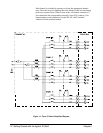
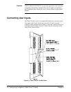
Basic Operation As shown in Figure 1-1, the Form C Switch consists of 16 channels
(channels 00 through 15). Each channel uses a latching relay. As required,
jumpers can be added to connect +5 V or +12 V for control or digital output
applications. Also, pullup resistors can be added for digital output
applications.
Chapter 1 Getting Started with the Agilent E1364A 11