


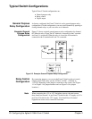
Digital Output
Configuration
By connecting jumpers and installing pullup/pulldown resistors, you can
configure the switch as a digital output device.
Note When connecting the + 5V or + 12V backplane sources for digital output
operation, you must install pullup resistors on the Form C Switch for the
supplies used. Also, the total current drawn by user circuits should not
exceed 1 A per Form C Switch for the + 5V supply or 0.5 A per Form C
Switch for the + 12V supply. You should fuse all external equipment to
ensure excess current is not drawn.
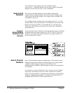
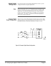
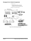
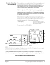
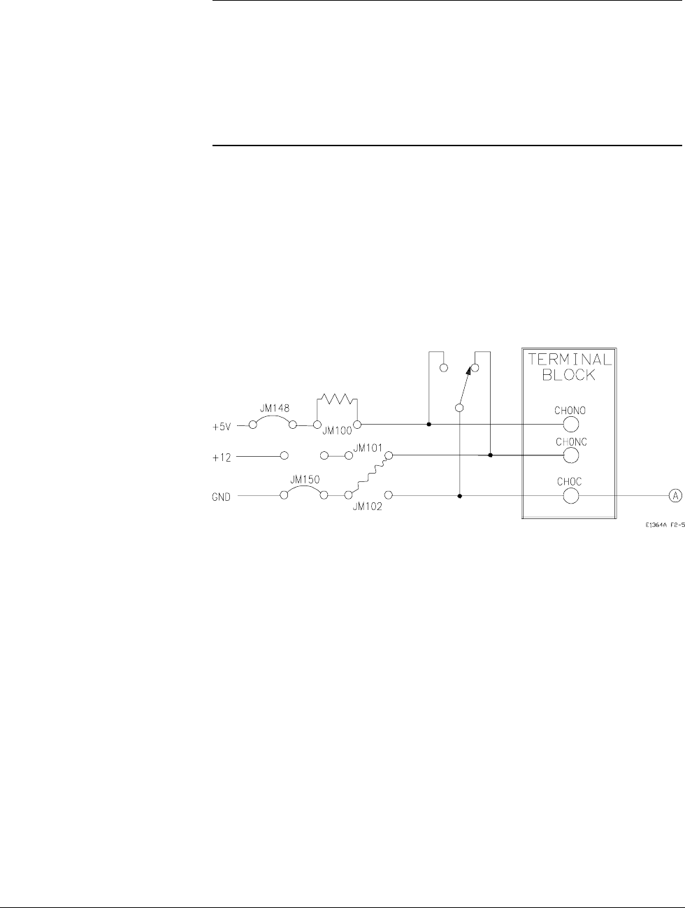
Example: Digital
Output Configuration
Figure 2-5 shows channel 00 configured for digital output operation. When
the channel 00 relay is open (NC connected to C), point A is at + 5V. When
the channel 00 relay is closed (NO connected to C), point A is at 0V.
Figure 2-5. Example: Digital Output Configuration
22 Configuring the Agilent E1364A Form C Switch Chapter 2