


Example: Scanning
With External Devices
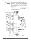
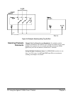
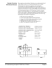
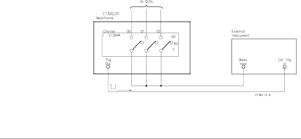
This example uses the mainframe Trig Out port to synchronize the Form C
Switch channel closures to an external measurement device. See the
following figure for typical user connections. For measurement
synchronization, the Agilent E1300B/E1301B Trig Out BNC port is
connected to the instrument External Trigger In port. For this example, the
mainframe and instrument are connected via GPIB with mainframe address
of 709 and instrument address of 722. The Form C Switch is at logical
address 120 (secondary address 15). The measurements are transferred
directly to the computer. (Appropriate instrument commands must be added
to line 10 and you may need to add a WAIT statement as line 65 for long
measurements.) The sequence of operation is:
1. INlT (line 50) closes channel 100.
2. Closure causes trigger output from the Trig Out port.
3. Trigger to Ext Trig In initiates channel 100 measurement.
4. Result is sent to the computer (lines 60-80).
5. TRIGGER (line 90) advances the scan to channel 101.
6. Steps 2-5 are repeated for channels 101-102.
10 OUTPUT 722; "TRIG EXT;...." ! Configure instrument
20 OUTPUT 70915; "0UTP ON" ! Enable Trig Out port
30 OUTPUT 70915; "TRIG:SOUR BUS" ! GPIB bus triggering
40 OUTPUT 70915; "SCAN (@100:102)" ! Scan channels 00-02
50 OUTPUT 70915; "INIT" ! Enable scan
60 FOR I = 1 TO 3 ! Start count loop
70 ENTER 722;A ! Enter reading
80 PRINT A ! Display reading
90 TRIGGER 70915 ! Advance scan
100 NEXT I ! Increment count
110 END
36 Understanding the Agilent E1364A Form C Switch Chapter 4