


User Manual: Family of 8-bit Digitizers Page 50 of 66
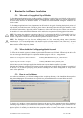
where the data is located, select the output format and click OK.
All binary data files found in the source directory will be converted to the desired format. If you are writing
amplitudes with multiple segments, formatting with segments in columns is limited to 200 segments.
4.6. Calibrate
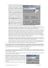
The Calibrate item in the Options menu leads to a sub-menu where a particular type of calibration can be invoked. In
order to use this item the acquisition must be stopped; otherwise the Calibrate option is not selectable. The
possibilities are
Calibrate instruments - to perform a self-calibration on the digitizers, calibrating the gain, offset, trigger
level and the timing. Performing a calibration compensates for any drift in these properties, typically due to
component temperature variations.
Calibrate current combine configuration – to perform a calibration only at the current configuration in each
instrument.
Calibrate External Clock Timing – to do a calibration of the internal TDC in the Continuous External Clock
mode.
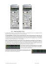
4.7. Combine channels
The Combine Channels function in the Options menu gives the
DC135/DC140/DC241/DC241A/DC271/DC271A/DC271AR/DP235/DP240 user the control of how many
converters will be used for each channel. This allows the memory size and the sampling rate to be increased in
situations where not all of the input channels need to be acquired. Normally digitizer modules work with one
converter/channel. If two or more converters/channel are desired, the identities of the channels to be used have to be
chosen with the Active Channel control.
4.8. External 10 MHz Reference and External Clock
Either one of the External 10 MHz Reference or External Clock options can be selected in the Options Menu. The
external input threshold option, available in the options menu, must also be set appropriately. The 10 MHz Reference
can be activated at the I/O B output.
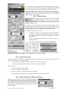
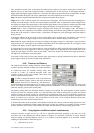
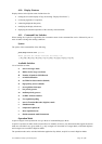
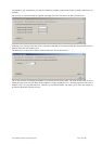
The External Clock function is available in AcqirisLive only when using the control panel in Transient Recorder
mode. The input frequency should be keyed into the clock frequency selector (outlined in red) on the control panel.
Then the appropriate sampling frequency must be selected in order for the proper timebase to be displayed on the
waveform display window. The time window displayed can be manipulated by allocating more or less memory to the
acquisition.
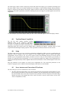
The External 10 MHz Reference in AcqirisLive is designed to work either in Oscilloscope mode or in Transient
Recorder mode. The timebase and sample rate for waveform capture is fully selectable when using the external
reference, just as it is when using the digitizer’s own internal reference clock.
4.9. Additional Waveform Information
The Options menu also includes possibilities to obtain additional information about the waveform. In both cases
described below the display will be updated after each acquisition.
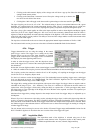
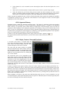
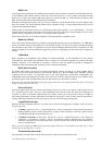
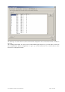
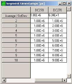
The “Show Segment Timestamps” option shows a display like the one below:
It gives you the information needed to better understand the trigger times of the
individual segments of an acquisition. By definition the first trigger of an
acquisition occurs at t
1
=0.0. There are two columns for each digitizer. For the n’th
row, the first column contains the difference t
n
– t
n-1
and the second column
contains t
n
. The top line contains the average value of the t
n
in the left column and
the standard deviation of the t
n
in the right one. The times are in ps.
The “Show Parameters” option activates a display of pulse parameters for each
active channel. Inactive channels will have parameter values of 0.0. The parameters
will be calculated in a model in which the distribution of measured voltages has
two distinct peaks. If this condition is not satisfied the results will be unreliable.