


15
Service
Service
Service for the N1022A Active Probe Adapter is by replacement only. To order
a new N1022A, contact your local Agilent Technologies Sales Office. Return
the failed probe adapter to your local Agilent service center.
If the probe adapter is still under warranty or is covered by an Agilent mainte-
nance contract, it will be replaced under the terms of the warranty or con-
tract.
Refer to “Agilent Technologies Service Offices” on page 17 to contact the Agi-
lent Call Center or your local service center.
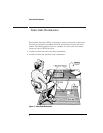
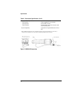
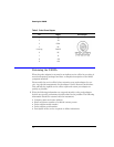
Checking Probe Power Outputs
The probe power output is located on the front panel of the probe adapter,
surrounding the BNC input.
Use Table 5 on page 16 to check the power output at the connectors. The DCA
module provides the probe adapter with +17V and -17V supplies. The probe
adapter generates the +12 V and -12 V supplies and the +3 V and -3 V sup-
plies.
Measure the voltages with respect to the DCA mainframe’s front panel ground
connector (located above the power switch) or the outside conductor of the
Cal BNC connector.
CAUTION Do not attempt to measure voltages at pins 3 through 7.
Any failure may be a problem with the probe adapter assembly.