


Features and Functions 3
U2781A User’s Guide 33
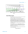
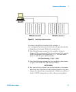
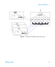
Figure3-4 Block diagram of the 10 Mhz Reference Clock and External
Trigger In
System Reference Clock
The 10 MHz reference clock can come from two sources; internal
backplane oscillator and external clock source.
The internal oscillator on the USB backplane supplies an
independent 10 MHz system reference clock to each of the USB
slot. This 10 MHz reference clock is driven through an
independent buffer. Refer to Figure 3- 4 for the block diagram.
Every clock trace is in equal distance to ensure that the slot to
slot skew is at minimum. Users can use this common reference
clock signal to synchronize multiple modules in a measurement
or control system.
The default SCPI command of ACQuire:RSIGnal AUTO will
scan thru and detect if there is any valid clock source from the
external BNC connector. If non is found, then the internal 10
MHz clock source will be used.
The SCPI command below will direct the reference clock source
to the internal 10 MHz:
ACQuire:RSIGnal INT