


User’s Manual
AirLink Communications, Inc. August 9, 2001 Page 23
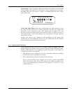
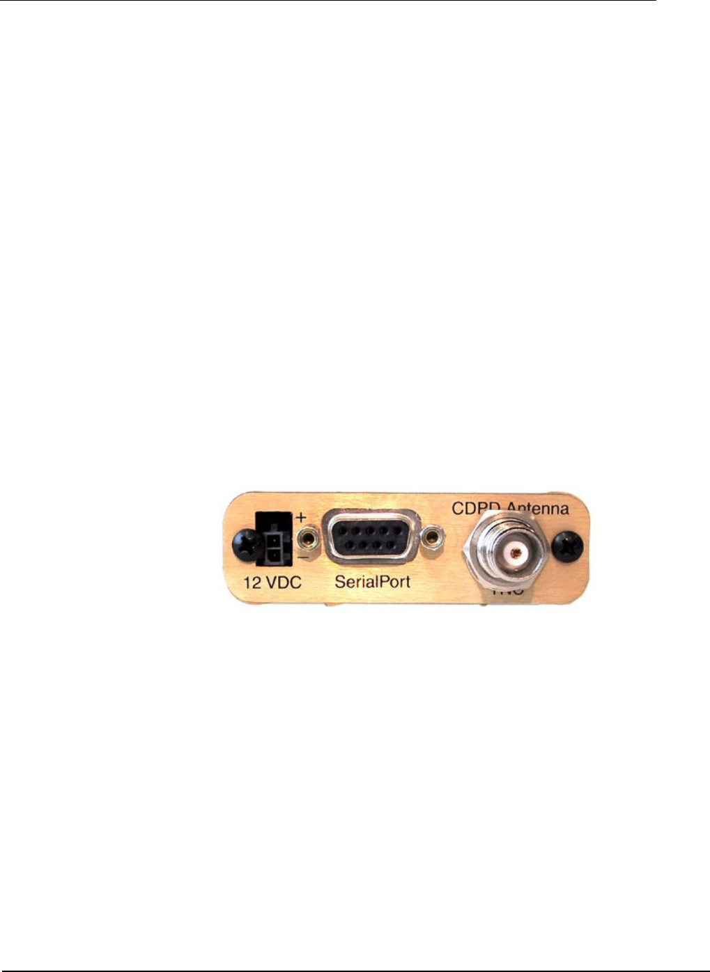
Connecting the antenna
Install an appropriate external cellular antenna. Connect the antenna to the
external jack of the bulkhead jack adapter with an appropriate RF cable.
Connect the Raven antenna jack to the interior bulkhead jack with an
appropriate RF cable.
Connecting the serial cable
Connect the RTU/PLC meter serial port to the Raven serial port with a DB-9
male connector.
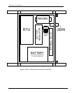
Grounding the Raven Case
The exterior Raven II case should be connected to the enclosure ground which
should be connected to the battery or power source negative terminal. This is
best accomplished with a grounding strap under one of the mounting bracket
screws to the enclosure grounding bar.
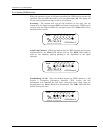
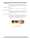
Connecting the power cable
The power cable positive lead should be connected to the battery or power
source positive terminal. The power cable negative lead should be connected
to the battery or power source negative terminal. The Raven II has an
internal polysilicon circuit breaker that opens at 0.5 to 1.0 amps of current.
Insert the power connector into the Raven II power receptacle.
Figure 3 - Raven II Back Panel