


8
19-inch equipment rack. To do this, first install the mounting
brackets on the Switch’s side panels (one on each side),
secure them with the included screws, and then use the
screws provided with the equipment rack to mount the
Switch.
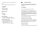
2.4 Power on the Switch
The Switch has a universal power supply ranging from 100V
to 240V AC, 50 ~ 60Hz power source. The AC power
connector is located at the rear of the unit adjacent to and the
system fan. The switch’s power supply will adjust to the local
power source automatically.
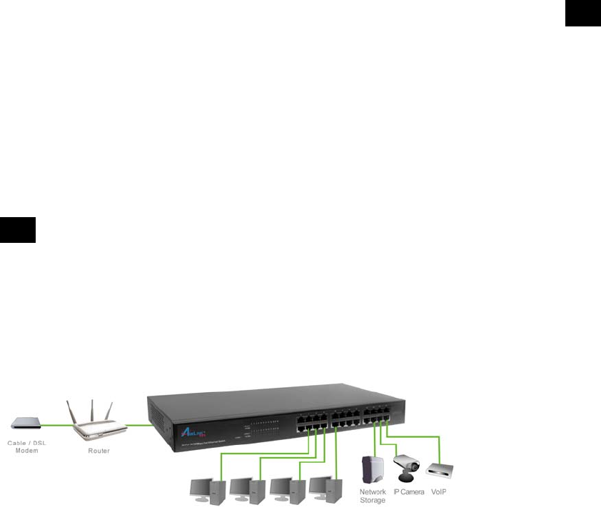
3 Connecting the Switch
This section describes how to connect the Switch to your
10/100Mbps Fast Ethernet network.
3.1 Connection
Your network device (i.e. computer, switch, IP Camera, VoIP)
can be connected to any port of the Switch via a two-pair
Category 5 Cable. If the LED indicators do not light up after
9
making a proper connection, check your network device, the
cable, the Switch conditions and connections.
4 Technical Support
E-mail: support@airlink101.com
Toll-Free: 1-888-746-3238*
Web Site: www.airlink101.com
* Free Voice Technical Support is only available within the hardware warranty
(1-Year Limited Warranty from the date of purchase). Customer is required to
provide invoice as purchase evidence.
**Network conditions and environmental factors as well as network overhead
lower actual data throughput rate.
Copyright © 2009 AirLink101. All rights reserved. AirLink101, the stylized
AirLink101 logo, specific product designations, and all other words and logos that
are identified as trademarks and/or service marks are, unless noted otherwise,
the trademarks and service marks of AirLink101. All other product or service
names are the property of their respective holders. AirLink101 products are
protected under numerous U.S. and foreign patents and pending applications,
mask work rights, and copyrights.