


EC-1 AES/EBU Interface, Appendix E
E-6 EC-1 MANUAL 1.00
INSTALLATION
PRECAUTIONS
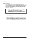
Install the EC-1 only if you have had some experience with similar devices
and feel competent to do so. If the following instructions are not clear
to you, have your dealer or a trained technician install it for you.
Hazardous voltages are present within the chassis. Do not remove the top
panel without first unplugging the unit from AC power!
EC-1 CONNECTION TO M20 MAIN CIRCUIT BOARD
The EC-1 comes with a 40-pin flexible cable. The cable should be attached to the multi-pin
header on the card with the blue side of the cable facing away from the XLR connectors.
To connect the EC-1 to the M20:
1. Remove the top panel from the M20. The top panel is held to the rear panel with two
Philips head screws.
2. Remove the expansion slot blank panel from the M20 rear panel. Four screws keep the
blank panel in place. It is best to hold the blank panel in place when removing the
screws to prevent the blank from dropping onto the main circuit board.
3. Insert the ribbon connector into the 40-pin header on the main circuit board. The
header is labeled “J7” and sits to the right of the chip labeled “2-32-0007 SMPTE
FPGA”. The blue side of the cable should face the front of the M20.
4. Screw the EC-1 card into the expansion slot from the inside of the M20. Use the four
screws that held the blank panel in place.
5. Replace the top panel.
To test for proper installation, plug the unit back in to AC power, turn on the M20, and
press the Digital Source button (next to the meter display) until the “DIG SOURCE” group
in the meter display indicates “I/O CARD”. This confirms that the M20 has detected the
EC-1’s presence.