


Quick Install Guide 5
C613-04017-01 REV H
Installing the Switch
All AC and DC versions of this equipment must be earthed.
Follow these steps to install the switch:
1. Before installing the switch, read the safety information
For safety information, see the Safety and Statutory Information booklet. A
copy of this booklet is supplied with each switch, and can also be found on
the Documentation and Tools CD-ROM or at www.alliedtelesyn.co.nz/
support/rapier/.
2. Gather the tools and equipment you will need
If installing a DC version of the switch, you will need a DC power source,
DC supply cable, and wire strippers (see step 7).
If the switch is to be connected to a redundant power supply, you will need
a redundant power supply unit and cable (see step 9).
3. Unpack the switch
Verify the package contents. If any items are damaged or missing, contact
your sales representative.
4. Install expansion options
If you purchased optional Uplink Modules, a Network Service Module
(NSM), or Port Interface Cards (PICs), install them now by following their
individual installation guides. These guides can be found on the
Documentation and Tools CD-ROM.
5. Place the switch in its operating location
See the previous "Selecting a Site" section for guidelines on choosing a
suitable location. If installing the switch in a rack:
• Remove the rubber feet.
• Attach the rack-mounting brackets.
• Mount the switch in the rack.
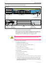
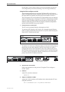
6. Apply AC power to the switch (for AC models)
Plug the power cord into the AC power connector on the switch’s rear
panel (see Figure 1). The Fault LED should flash for approximately 10
seconds as the switch runs internal tests. If the LED continues to flash or
remains lit, refer to the Rapier Switch Hardware Reference for troubleshooting
information.