


Quick Install Guide 7
C613-04017-01 REV H
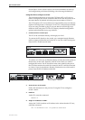
d) At the switch, connect the positive feed to the + (positive) terminal and
the negative feed to the - (negative) terminal. Tighten the terminals to
between 0.6 and 0.8 Nm (0.041 to 0.055 pound-force per foot)
e) Ensure there are no exposed conductor strands
f) Secure the supply cable (to the rack framework or similar object) so the
connections are isolated from any force applied to the cable
g) Ensure the circuit breaker is in the Off position
h) Connect the supply-cable wires to the circuit breaker
i) Energise the circuit breaker
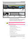
Figure 2: DC Power inlet terminals on a Rapier 24.
The Fault LED should flash for approximately 10 seconds as the switch
runs internal tests. If the LED continues to flash or remains lit, refer to the
Rapier Switch Hardware Reference for troubleshooting information.
8. Check that the Power LED on the switch’s front panel lights green
If the LED fails to light, refer to the Rapier Switch Hardware Reference for
troubleshooting information.
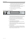
9. Connect the Redundant Power Supply (Optional)
AC models of Rapier Switches have a Redundant Power Supply (RPS)
connector on their rear panel (see Figure 1).
The Switch is designed to operate with the AT-RPS8000 RPS, which can be
purchased separately. Contact your authorised Allied Telesyn distributer
or reseller for more information.
10. Connect the data cables
Use straight-through or cross-over Ethernet patch cables to connect the
required device(s) to the switch’s ports. Make sure each cable connection is
secure. The switch will now perform basic Layer 2 switching functions. By
default, all switch ports are members of VLAN1.
NSM 0
Hot Swap
In Use
Swap
38-75VDC , 2A
FOR CENTRALIZED DC
POWER CONNECTION,
INSTALL ONLY IN A
RESTRICTED AREA
DC Power inlet
DC INPUT