


6 Rapier Series Switch
C613-04017-01 REV H
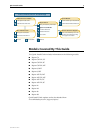
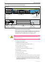
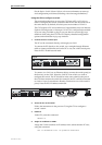
Figure 1: Rapier front panel and rear panel with AC power inlet.
7. Apply DC power to the switch (for DC models)
Read the Safety and Statutory Information booklet before connecting a DC
power supply. A copy of this booklet is included with each switch. It is also
included on the Documentation and Tools CD-ROM, or can be
downloaded from www.alliedtelesyn.co.nz/support/rapier/.
Only trained and qualified personnel should connect a DC power supply. Due
to exposed terminals, DC powered switches should be installed only in
Restricted Access Areas.
DC supply cable specifications:
• Number of wires (cores): 3
• Minimum size: 2.1mm
2
(14 AWG)
• Minimum cable rating: 600V, 90 degrees Celsius
DC power supply specifications:
• 48 VDC (39-60 VDC is acceptable)
• Either positive grounded or negative grounded
Circuit protection:
• Use a 10 Amp circuit breaker
To connect the DC supply:
a) Ensure the supply cable is not live
b) Strip the supply cable wires to expose 8mm (0.31 in.) of bare conductor
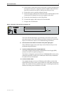
c) At the switch, connect the ground wire to the ground terminal. These
terminals can be identified by the diagram on the switch’s rear panel
(see Figure 2). Tighten the terminal to between 0.6 and 0.8 Nm (0.041 to
0.055 pound-force per foot)
STAT US
RESET
FAU LT
PWR
RPS
1
2
3
4
5
6
7
8
9
10
11
12
13
14
15
16
17
18
19
20
21
22
23
24
10BASE-T / 100BASE-TX
1X 3X 5X 7X
2X 4X 6X 8X
9X 11X 13X 15X
10X 12X 14X 16X
17X 19X 21X 23X
18X 20X 22X 24X
25
26
RS-232
TERMINAL PORT
100M LINK / ACTIVITY 10M LINK / ACTIVITY
HALF DUP/
COL
FULL DUP
PORT ACTIVITY
L/A
L/A
D/C
D/C
L/A
D/C
ASYN0
Layer 3 Fast Ethernet Switch
NSM 0
Hot Swap
In Use
Swap
Front panel
Uplink Module Bays
10/100 BASE Ports
Port LEDs System
LEDs
RS-232 Terminal Port
Rear panel
100-240 VAC
Power Inlet
RPS Inlet for
AT-PWR8000
NSM BAY NSM Hot Swap
Button and LEDs