


8
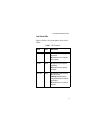
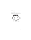
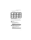
Figure 5 illustrates a network of two AT-
FS705LE Ethernet Switches that have been
interconnected using the Uplink ports on the
two units. Using the Uplink ports eliminates
the need for a cross-over cable to interconnect
the switches.
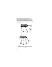
Figure 5 Multiple AT-FS705LE Ethernet Switch
Topology
Uplink
54
3
2
1
Uplink
54
3
2
1