


Quick Install Guide 11
C613-04017-01 REV H
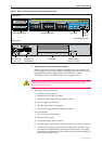
1. DC models of the Rapier Switch do not have an RPS connector and the RPS LED will not function.
2. Not included on the Rapier 48, G6, G6F-SX/SC, G6F-LX/SC, or G6F-SX/MT-RJ.
3. Hot swapping is supported by Software Release 2.3.1 or later. AT-AR021 (S) BRI-S/T, AT-AR021 (U)
BRI-U, and AT-AR023 SYN PICs can be hot swapped.
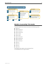
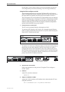
The Rapier Switch Hardware Reference has further troubleshooting information,
including information on Switch Port and Uplink Module LEDs.
Documentation and Tools CD-ROM
The Documentation and Tools CD-ROM bundled with each Rapier Switch
contains the complete Documentation Set for your switch and its expansion
options, as well as tools for managing the switch. This includes:
■ The Rapier Switch Statutory and Safety booklet, which provides safety and
statutory information for the Rapier Switch and its expansion options.
■ The Rapier Switch Hardware Reference, which provides detailed information
on the hardware features of Rapier Switches.
■ This Quick Install Guide.
■ The Rapier Switch Software Reference, which provides detailed information
on configuring the switch and its software.
■ The Network Service Module Quick Install Guide, which outlines the
procedure for installing an NSM; and the Network Service Module Hardware
Reference, which provides detailed information on NSMs.
■ The Port Interface Card Quick Install Guide, which outlines the procedure for
installing PICs; and the Port Interface Card Hardware Reference, which
provides detailed information on PICs.
■ The Uplink Module Quick Install Guide, which outlines the procedure for
installing an Uplink Module; and the Uplink Module Hardware Reference,
which provides detailed information on Uplink Modules.
■ AT-TFTP Server for Windows for downloading software releases.
■ Adobe Acrobat Reader for viewing online documentation.
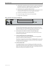
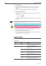
RPS
1
(Redundant
Power Supply)
Green An RPS is connected to the switch
In use
2
(Rear panel)
Green An NSM is installed, is receiving power, and is
operational. The NSM and its PICs are not
ready to be hot swapped
Off No NSM is installed, or the NSM is not installed
correctly (the switch unit has not recognised
the NSM)
Swap
2
(Rear panel)
Green The NSM and its PICs are ready to be hot
swapped
Off The Hot Swap button must be pressed before
the NSM or PICs can be hot swapped, or the
software release does not support hot
swapping
3
System LEDs
LED State Function