


AT-9400 Series Gigabit Ethernet Switches Installation Guide
41
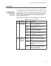
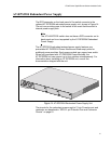
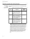
AT-RPS3204 Redundant Power Supply
The RPS connector on the back panel of the switch connects to the
optional AT-RPS3204 redundant power supply unit, shown in Figure 14.
The unit can provide power to the switch in the event that the switch’s
internal power supply fails.
Note
The AT-9424T/POE switch does not have a RPS connector on its
back panel and is not supported by the AT-RPS3204 Redundant
Power Supply.
The AT-RPS3204 redundant external power supply features one
preinstalled AT-PWR3204 Power Module and three empty slots for
additional power modules. Each power module can support one switch.
When fully populated with AT-PWR3204 Power Modules, the
AT-RPS3204 unit can support up to four switches simultaneously. For
information about installing an AT-RPS3204 unit, consult the
documentation shipped with the unit.
Figure 14 AT-RPS3204 Redundant Power Supply Unit
The pinouts for the redundant power supply’s 21-pin D-combo port and
connector are described in “RPS 21-pin D-combo Port and Connector
Pinouts” on page 81.
AT- P W R3204
POWER