


AT-FS705E FC and AT-FS706E FC Installation Guide
21
The AT-FS705E FC switch has one 100FX DUPLEX switch for its one fiber
optic port. The AT-FS706E FC switch has two switches for its two fiber
optic ports.
7. Power ON the end nodes connected to the ports on the switch.
8. Check the LNK/ACTY LED for each port. The LED should be steady green
or blinking. If a LNK/ACTY LED remains OFF, refer to “Verifying and
Troubleshooting the Installation” on page 22 for assistance.
Installing the Switch on a Wall
The switch can be mounted either vertically or horizontally on a wall using
the keyholes on the bottom of the chassis.
Note
For wall-mount installation, you must supply the two screws and plastic
anchors or other material necessary to mount the device on the wall.
To install the switch on the wall, perform the following procedure:
1. Remove the rubber feet, all cables, and the DC power cord from the switch.
2. Select a wall location for the device.
3. Install two plastic anchors and two pan-head screws into the wall,
separated by 100 millimeters (3.94 inches).
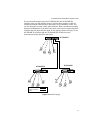
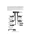
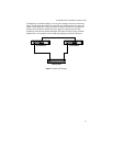
4. Position the device onto the wall screws. If you are mounting the switch
horizontally, position the switch so that the ports are facing down and the
LEDs are facing up. If you are mounting the switch vertically, position the
switch so that the ports are facing to the left and the LEDs to the right.
5. Power ON the switch using the external power adapter supplied with the
unit. Connect the external power adapter to an appropriate power source
and the DC cable on the adapter to the DC connector on the switch.
The PWR LED on the switch’s front panel should be ON. If the LED
remains OFF, refer to “Verifying and Troubleshooting the Installation” on
page 22 for assistance.
Warning
The power cord is used as a disconnection device. To de-energize
equipment, disconnect the power cord. 9