


22
Note
To prevent the DC power cable from being inadvertently pulled out of
the switch, use the cable tie supplied with the unit to secure the DC
power cable to the small cable hook located next to the DC connector.
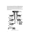
6. Connect the twisted pair cables to the RJ45 connectors on the switch.
7. Remove the dust cover from the fiber optic port and connect the fiber optic
cable to the port.
8. Set the 100FX DUPLEX switch to either HALF for half-duplex or FULL
for full-duplex operation. The capabilities of the end node connected to the
fiber optic port will determine the correct setting for this switch. If the end
node is capable of only half-duplex, set the switch to HALF. If the end node
is capable of full-duplex, set the switch to FULL.
The AT-FS705E FC switch has one 100FX DUPLEX switch for its one fiber
optic port. The AT-FS706E FC switch has two switches for its two fiber
optic ports.
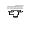
9. Power ON the end nodes connected to the ports on the switch.
10. Check the LNK/ACTY LED for each port. The LED should be steady green
or blinking. If a LNK/ACTY LED remains OFF, refer to “Verifying and
Troubleshooting the Installation.” for assistance.
Verifying and Troubleshooting the Installation
This section contains information on how to verify the installation of the
switch and how to troubleshoot the unit in the event a problem occurs.
Check the PWR LED on the front of the switch. If the LED is OFF, indicating
that the unit is not receiving power, do the following:
Make sure that the power adapter is securely connected to a power
source and that the DC power cord on the adapter is securely
connected to the DC power connector on the switch.
Verify that the power outlet has power by connecting another device
to it.
Try connecting the unit to another power source.
Try using another power adapter.