


AT-GS900/16, AT-GS900/24 Gigabit eco-friendly Ethernet Switch Installation Guide
35
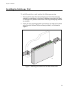
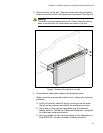
3. Place the switch on the wall. Then mount the switch using the plastic
anchors and screws which are shipped with the product. See Figure 8.
Warning
The switch must be mounted with the AC Power Connector facing
down to conform with UL requirements as shown in Figure 8.
Figure 8. Attaching the switch to the wall
4. Connected the twisted pair cables to the twisted pair ports.
When connecting a twisted pair cable to a port, observe the following
guidelines:
An RJ-45 connector should fit snugly into the port on the switch.
The tab on the connector should lock the connector into place.
Check that you are using the appropriate type of twisted pair
cabling. Refer to “Twisted Pair Cabling and Distances” on page 30
for twisted pair cable specifications.
Since the twisted pair port, when operating in Auto-Negotiation, is
Auto MDI/MDI-X, you can use either a straight-through or
1925
24 P
o
rt 10/100/1000B
ase-T Gig
abit E
ther
net
Switch
1 3 5
7
91
1
1
31
5
1
7
1
9
2
12
3
2
4
6 8 1
0
1
2
1
4
1
6
1
8
2
0
2
2
2
4
1
8
2
0
2
2
2
4
1
01
2
1
4
1
6
2
4
6 8
91
1
1
3
1
5
1
3
5
7
1
71
9
2
1
2
3
POW
ER
1
0
/1
0
0
L
IN
K
A
C
T
1
0
0
0
L
I
N
K
A
C
T
F
D
X
H
D
X
COL
A
T-
G
S
9
0
0
/2
4