


Chapter 1: Overview
44
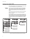
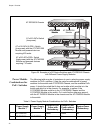
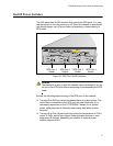
Power Module
Status LEDs
For general status information about the power supply modules, refer to
the FAN and DC OUT LEDs in the Power Module Status section of the
LED panel.
Figure 29. Power Module Status LEDs
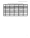
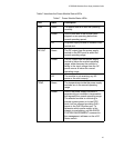
CABLE Green The RPS port is enabled and connected
to an x610 Series switch, and the power
supply module is powered on.
Amber The RPS port is not connected to an x610
Series switch.
Off This LED state indicates one of the
following:
The RPS port is disabled.
The power supply slot is empty.
The power supply module is not
powered on.
The power supply module has failed.
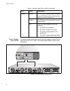
Table 6. Module A and B Ports LEDs (Continued)
LED State Description
B
B
1
2
3
4
SYSTEM
PoE+ / SYSTEM PoE+ / SYSTEM
SYSTEM
MODULE B
MODULE A
A
A
AT-PWR800
DC OUT
FAULT
100-240 VAC~12A MAX
AT-PWR800
DC OUT
FAULT
100-240 VAC~12A MAX