


AT-RPS3000 Redundant Power Supply Installation Guide
89
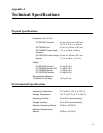
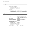
Port Pin-outs
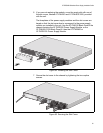
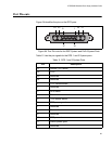
Figure 64 identifies the pins on the RPS ports.
Figure 64. Port Pin-outs for the RSP System and PoE+/System Ports
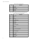
Table 11 lists the pin signals for the RPS 1 and 3 System ports.
Table 11. RPS 1 and 3 System Ports
Pin Description
P1 Ground (12V return)
P2 +12V
P3 Reserved
P4 Reserved
1 +12V remote sense
2Reserved
3 RPS status
4Reserved
5 -12V remote sense
6 RPS power good
7Reserved
8Reserved
9Reserved
10 RPS present
11 Switch power good
12 Reserved
P1P2P3P4
19
1017