


AT-RPS3000 Redundant Power Supply Installation Guide
65
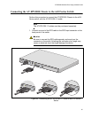
Connecting the AT-RPS3000 Chassis to the x610 Series Switch
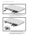
Perform this procedure to connect the AT-RPS3000 Chassis to the x610
Series switch, with the AT-RPS-CBL1.0 cable:
Note
The AT-RPS-CBL1.0 cables must be purchased separately.
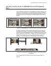
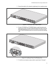
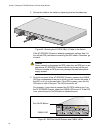
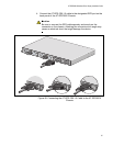
1. Connect one end of the RPS cable to the RPS Input connector on the
back panel of the switch.
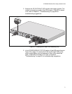
Caution
Be sure to connect the RPS cable squarely and evenly on the
connector on the switch. Attaching the connector at an angle may
cause an electrical short that might damage the device.
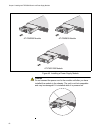
Figure 45. Connecting the AT-RPS-CBL1.0 Cable to the x610 Series
Switch
STAC
KING
A
A
AT-PWR800
D
C O
UT
FA
U
LT
POWER SUPPLY
R
P
S
R
E
A
D
Y
RP
S
IN
P
U
T
WA
R
N
I
N
G
T
h
i
s
u
n
i
t
m
a
y
h
a
v
e
m
o
r
e
t
h
a
n
o
n
e
p
o
w
e
r
i
n
p
u
t
.
T
o
r
e
d
u
c
e
t
h
e
r
i
s
k
o
f
e
le
c
t
r
i
c
s
h
o
c
k
,
d
i
s
c
o
n
n
e
c
t
b
o
t
h
A
/
C
a
n
d
R
P
S
i
n
p
u
t
s
b
e
f
o
r
e
s
er
v
i
c
i
n
g
u
n
i
t
.
12
V/21
A M
A
X
2132
POWER SUPPLY
RPS
REA
D
Y
RPS INPUT
W
A
R
N
IN
G
T
h
is
u
n
it ma
y
h
a
v
e
m
o
re
th
an
o
n
e
p
o
w
e
r
in
p
u
t.
To r
e
d
u
ce
th
e
ris
k
o
f
e
le
c
tric
s
h
o
c
k
,
d
is
c
o
n
n
e
c
t
b
o
t
h
A/C
a
n
d
R
P
S
in
p
u
ts
b
e
fo
r
e s
e
rv
ic
in
g
u
n
it
.
12V/21A
MAX
POWER SUPPLY
RPS
REA
D
Y
RPS INPUT
W
A
R
N
IN
G
T
h
is
u
n
i
t ma
y
h
a
v
e
m
o
re
th
an o
n
e
p
o
w
e
r
in
p
u
t.
To
r
e
d
u
ce
th
e
r
isk
o
f
e
le
c
tric
s
h
o
c
k
,
d
is
c
o
n
n
e
c
t
b
o
th
A
/C
a
n
d
R
P
S
in
p
u
ts
b
e
fo
r
e
s
e
r
v
ic
in
g
u
n
it
.
12V/21A
MAX
POWER SUPPLY
RPS
REA
D
Y
RPS INP
UT
W
A
R
N
IN
G
T
h
is
u
n
it ma
y
h
a
v
e
m
o
re
th
an
o
n
e
p
o
w
e
r
in
p
u
t.
To r
e
d
u
c
e
th
e
r
is
k
o
f
e
le
c
tric
sh
o
c
k
,
d
is
c
o
n
n
e
c
t
b
o
th
A/C
a
n
d
R
P
S
in
p
u
ts
b
e
fo
r
e
s
e
rv
ic
ing
u
n
it
.
12V/21A
MAX
100-240
VAC
~12A
MAX