


Chapter 4: Installing the Power Supplies
112
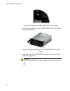
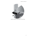
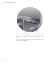
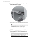
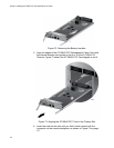
7. Lower the locking handle of the power supply module to secure the
module in the slot, as shown in Figure 68.
Figure 68. Locking the Handle on the AT-SBxPWRSYS1 Power Supply
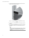
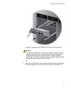
Note
Do not tighten the handle locking screw yet. You may need to
slightly lift the handle to move the plastic guard panel when you wire
the positive and negative wires in “Powering On the AT-
SBxPWRSYS1 DC System Power Supply” on page 161.
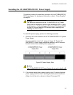
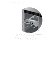
8. To install a second AT-SBxPWRSYS1 DC Power Supply, repeat this
procedure.
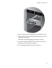
9. After installing the AT-SBxPWRSYS1 DC Power Supplies, go to
Chapter 5, “Installing the AT-SBx31CFC Card and Ethernet Line
Cards” on page 113.
Note
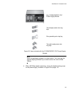
Retain the five wire ring lugs that come with the power supply. You
use them to wire the power supply in “Powering On the AT-
SBxPWRSYS1 DC System Power Supply” on page 161.