


SwitchBlade x3112 Installation Guide
63
Note
The AT-SBxPWRSYS1 DC Power Supply is not compatible with the
AT-SBxPWRSYS1 AC and AT-SBxPWRPOE1 AC Power Supplies.
Consequently, the chassis should not contain both AC and DC
power supplies. You may, however, operate the chassis for a short
period of time with AC and DC power supplies if you are converting it
from one type of power supply to another, such as from AC to DC.
This allows you to transition the chassis without having to power it
off.
Note
Given that the AT-SBxPWRSYS1 DC Power Supply is not
compatible with the AT-SBxPWRPOE1 AC Power Supply, a chassis
that contains one or more AT-SBx31GP24 PoE Line Cards should
use the AT-SBxPWRSYS1 AC Power Supply, and not the DC
module, as the system power unit.
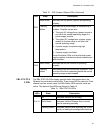
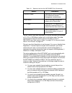
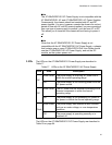
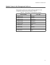
LEDs The LEDs on the AT-SBxPWRSYS1 Power Supply are described in
Table 17.
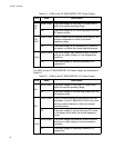
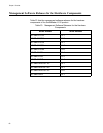
The LEDs on the AT-SBxPWRSYS1 DC Power Supply are described in
Table 18 on page 64.
Table 17. LEDs on the AT-SBxPWRSYS1 AC Power Supply
LED State Description
AC
Solid Green The power supply is receiving AC power that is
within the normal operating range.
Off The power supply is not receiving power from the
AC power source.
DC
Solid Green The DC power that the module is providing to the
chassis components is within the normal
operating range.
Off The power supply is not generating DC power or
the power is outside the normal operating range.
Fault
Solid Amber The power supply has detected a fault condition,
such as an under-voltage, or over-temperature
condition.
Off The power supply is operating normally or is
powered off.