


Chapter 8: Verifying the Hardware Operations of the Chassis
194
2. Compare the version number displayed by the SHOW SYSTEM
command with the information in Table 23 on page 68 to confirm that
the management software on the control card supports all the
hardware components in the chassis. If necessary, update the
management software on the control card. For example, if the control
card has release 14.2 and the chassis has one or more AT-SBx31XS6
Line Cards, which require release 15.1 or later, the line cards do not
forward network packets until you update the firmware on the control
card. For instructions, refer to the Software Reference for SwitchBlade
x3100 Series Switches.
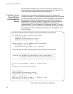
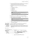
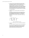
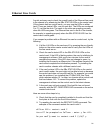
3. To display the status of the power supplies, enter the SHOW PSU
command.
An example of the status information is shown in Figure 146. The
power supplies are operating normally when the states are UP-UP. If
there is a problem with a power supply, refer to “AT-SBxPWRSYS1
and AT-SBxPWRPOE1 AC Power Supplies” on page 198 or “AT-
SBxPWRSYS1 DC Power Supply” on page 199 for troubleshooting
suggestions.
Figure 146. SHOW PSU Command
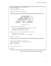
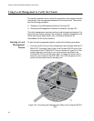
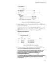
4. To display the state of the fan module, enter the SHOW FANMODULE
command.
The module is operating normally when its state is UP-UP-ONLINE, as
shown in Figure 147 on page 195. If the state of the fan module is
something other than UP-UP-ONLINE, power off the chassis and
contact your Allied Telesis representative for assistance. Do not
operate the chassis without a fully operational fan unit.
SHOW PSU
--- Power Supply Units ---
Slot Type State Temp (C)
A POE UP-UP 38
B POE UP-UP 38
C System UP-UP 38
D System UP-UP 38