


Chapter 7: Powering On the Chassis
170
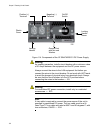
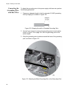
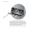
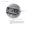
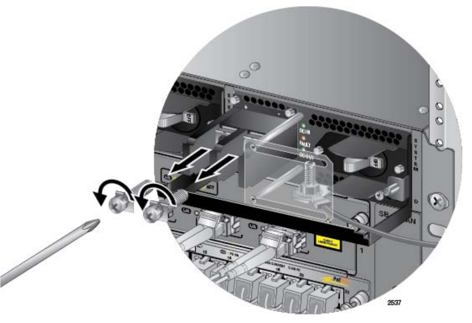
Figure 127. Removing the Terminal Screws
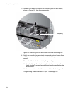
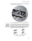
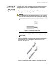
5. With a #3 Phillips-head screwdriver, connect the power lead wires to
the positive and negative terminals on the power supply, with the
terminal screws removed in step 4. The positive terminal is on the left
and the negative terminal is on the right. You may attach the terminals
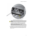
with the wires either above or below the terminal block. Figure 128 on
page 171 shows the wires above the terminal block.
Allied Telesis recommends tightening the screws to 30 to 40 inch-lbs.