


Chapter 3: Installing the Chassis in an Equipment Rack
80
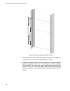
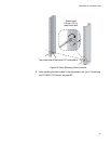
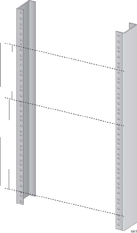
Figure 34. Reserving Vertical Rack Space
3. Identify the lowest 1/2” screw hole pattern on the rack mounting rails
within the space reserved for the AT-SBx3112 Chassis.
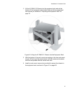
4. Install one rack mount screw in each vertical rail, at the same height in
the top screw hole of the lowest 1/2” hole pattern, as shown in Figure
35 on page 81. The screws are used to support the chassis while you
secure it to the rack. Do not fully tighten these two screws at this time.
The screw heads should protrude from the rack approximately 6.4 mm
(.25 in).
311.1 mm (12.25“)
152.4 mm (6”0)
463.5 mm (18.25”)