


SwitchBlade x3112 Installation Guide
49
AT-SBx31GC40
Line Card
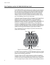
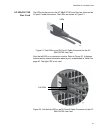
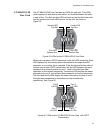
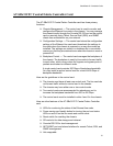
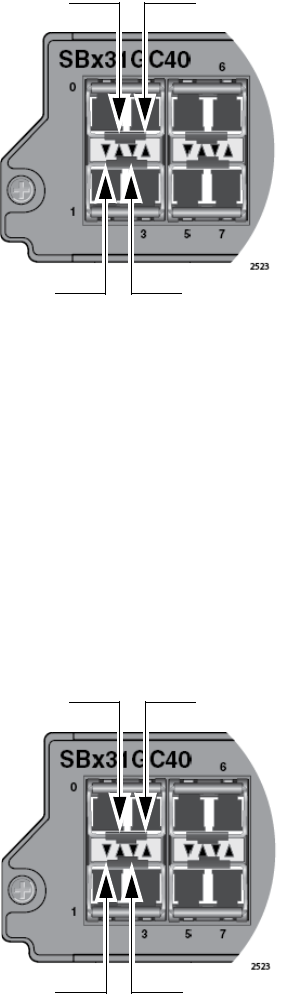
The AT-SBx31GC40 Line Card has two LEDs for each slot. The LEDS,
which display link and activity information, are located between the slots,
in sets of four. The first and third LEDs of each set are for the bottom slot
and the second and fourth LEDs are for the top slot, as shown in
Figure 25.
Figure 25. LEDs for the AT-SBx31GC40 Line Card
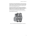
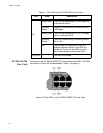
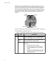
When a slot contains a CSFP transceiver, both slot LEDS are active. Each
LED displays link and activity status information for its respective BiDi
connector on a module. As an example, if the first top and bottom slots of
the line card contain CSFP transceivers, the first LED between the slots
displays link and activity status for port 1, which is the left-hand fiber
connector on the bottom transceiver. The second LED displays the same
information for port 0, the left-hand fiber connector on the top transceiver.
The third and fourth LEDs display the same information for ports 3 and 2,
the right-hand connectors on the bottom and top transceivers,
respectively. See Figure 26.
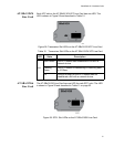
Figure 26. LEDs for the AT-SBx31GC40 Line Card, with CSFP
Transceivers
Second LED
Top Slot
Fourth LED
Top Slot
First LED
Bottom Slot
Third LED
Bottom Slot
Port 0
L/A LED
Port 2
L/A LED
Port 1
L/A LED
Port 3
L/A LED