


Chapter 3: Installing the Chassis in an Equipment Rack
90
Installing the Chassis Grounding Lug
This procedure explains how to connect a ground wire to the chassis. The
chassis requires a permanent connection for the line cards and power
supplies to a good earth ground. The procedure requires the following
items:
Grounding lug (pre-installed on the rear panel of the chassis)
#2 Phillips-head screwdriver (not provided)
Crimping tool (not provided)
10 AWG stranded grounding wire (not provided)
#2 Phillips-head 20 inch-lbs torque screwdriver (optional — not
provided)
To connect the chassis to an earth ground, perform the following
procedure:
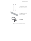
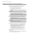
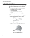
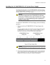
1. Prepare an adequate length of stranded grounding wire (10 AWG) for
the ground connection by stripping it as shown in Figure 43.
Figure 43. Stripping the Grounding Wire
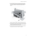
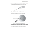
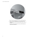
2. Remove the two screws that secure the grounding lug to the rear
panel of the chassis, as shown in Figure 44.
Figure 44. Removing the Grounding Lug