


Chapter 5: Installing the AT-SBx31CFC Card and Ethernet Line Cards
120
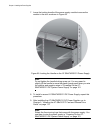
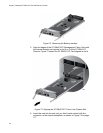
Installing the Ethernet Line Cards
This section contains the installation procedure for the Ethernet line cards.
The illustrations show the AT-SBx31GP24 Line Card, but the procedure is
the same for all the cards.
Caution
The electronic components on the line cards can be damaged by
electro-static discharges (ESD). Follow the procedure in “Protecting
Against Electrostatic Discharge (ESD)” on page 94 to guard against
ESD damage when unpacking and installing the line cards.
This procedure requires the following tools:
#2 Phillips-head screwdriver (not provided)
#2 Phillips-head, 5 inch-lbs torque screwdriver (optional — not
provided)
To install the Ethernet line cards, perform the following procedure:
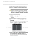
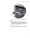
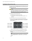
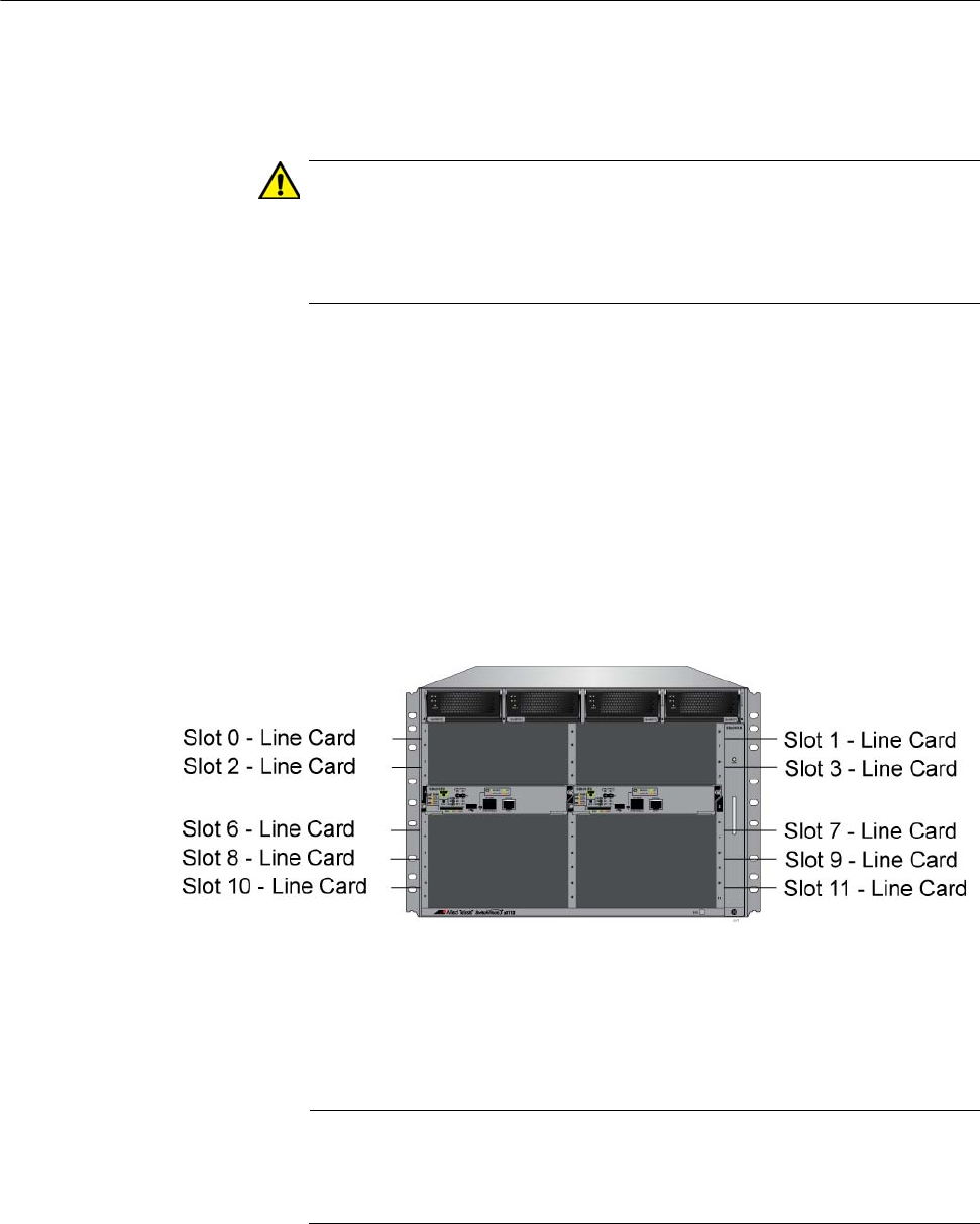
1. Choose a slot in the chassis for the Ethernet line card. The Ethernet
line cards may be installed in slots 0 to 3 and 6 to 11. The slots are
shown in Figure 77.
Figure 77. Slots 0 to 3 and 6 to 11 for the Ethernet Line Cards
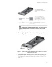
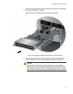
2. Remove the line card from the shipping package. If it is missing or
damaged, contact your Allied Telesis sales representative for
assistance.
Note
Store the packaging material in a safe location. You should use the
original shipping material if you need to return the unit to Allied
Telesis.