


Appendix A: Technical Specifications
220
Port Pinouts
This section lists the port pinouts for the AT-SBx31GT24, AT-SBx31GT40,
and AT-SBx31GP24 Line Cards.
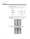
Figure 149 illustrates the pin layout for RJ-45 and RJ point 5 ports.
Figure 149. Pin Numbers for the RJ-45 and Point 5 Ports (Front View)
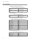
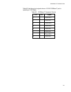
Table 40 lists the pin signals when a twisted-pair port is operating in the
MDI configuration.
Table 41 lists the port pin signals for the MDI-X configuration.
Table 40. MDI Pin Signals (10Base-T or 100Base-TX)
Pin Signal
1TX+
2TX-
3RX+
6RX-
Table 41. MDI-X Pin Signals (10Base-T or 100Base-TX)
Pin Signal
1RX+
2RX-
3TX+
6TX-
RJ45 Port RJ Point 5 Port